
Hardware reference guide

Intelligent/Special Purpose
35013379 02 October 2007 353
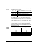
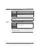
Command 4
Response
Format
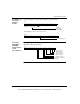
The following figures show the counters for 3X through 3X+5 for command 4.
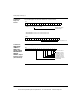
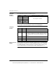
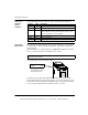
I/O Map Status
Byte
The most significant bit in the I/O Map status byte is used for the 140EHC20200
High Speed Counter Module. The following figure shows the map status byte
register.
16 15 14 13 12 11 10 9 8 7 6 5 4 3 2 1
3X
Read Rate Sample
/
Last Count
Command Byte
3X+1 and 3X+2 = Counter 1’s 32 bit Rate Sample / Last Count Before Preset.
3X+3 and 3X+4 = Counter 2’s 32 bit Rate Sample / Last Count Before Preset.
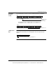
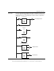
16151413121110987654321
3X+5
1 = Field Power Lost
87654321
1 = Internal Fuse Blown or External Output Supply Lost
This document provided by Barr-Thorp Electric Co., Inc. 800-473-9123 www.barr-thorp.com