
Hardware reference guide

Intelligent/Special Purpose
35013379 02 October 2007 351
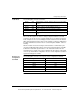
Command 1 and
Command 2
Response
Formats
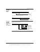
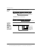
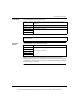
The following figures show the 3X through 3X+5 response formats.
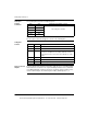
Command 3,
READ INPUT
COUNTER,
Output Register
Format
(4X = 03XX hex)
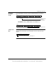
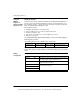
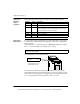
The following figure shows the 4X register for Command 3, READ INPUT
COUNTER, output register format.
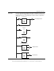
16151413121110987654321
3X
Configure or
Load Values
Command Byte
16151413121110987654321
3X+5
1 = Field Power Lost
3X+1 to 3X+4 echoes 4X+1 to 4X+4 register contents.
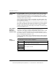
16151413121110987654321
4X
1 = Preset Counter 1
1 = Enable Counter 1
1 = Disable Counter 1
1 = Preset Counter 2
1 = Enable Counter 2
1 = Disable Counter 2
Read Counter Inputs Com-
mand Bits
This document provided by Barr-Thorp Electric Co., Inc. 800-473-9123 www.barr-thorp.com