
Hardware reference guide

Intelligent/Special Purpose
35013379 02 October 2007 347
Command 2.
LOAD VALUES,
Output Register
Format
(4X = 02XX hex)
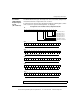
The LOAD VALUES 4X register format depends on the Counter/Rate Sample mode
selected in Command 1, Register 4X+1, bits 11 and 12.
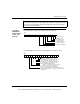
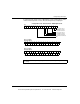
If configured for two 16 bit Counters, Output Assert ON, the following figures, which
shows counters for registers 4X through 4X+5, are displayed.
Note: Zero set into any 4X register means no change.
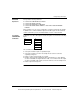
16 15 14 13 12 11 10 9 8 7 6 5 4 3 2 1
4X
1 = Enable Counter 1
1 = Disable Counter 1
1 = Preset Counter 2
1 = Enable Counter 2
1 = Disable Counter 2
Load Values Command
Bit
1 = Preset Counter 1
Maximum Count for Counter 1 (max = FFFF hex)
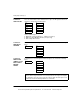
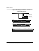
16 15 14 13 12 11 10 9 8 7 6 5 4 3 2 1
4X+1
Setpoint for Counter 1 (max = FFFF hex)
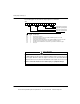
16 15 14 13 12 11 10 9 8 7 6 5 4 3 2 1
4X+2
Maximum Count for Counter 2 (max = FFFF hex)
16151413121110987654321
4X+3
Setpoint for Counter 2 (max = FFFF hex)
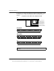
16 15 14 13 12 11 10 9 8 7 6 5 4 3 2 1
4X+4
Output Assert ON Time (milliseconds, max = 3FFF hex)
16 15 14 13 12 11 10 9 8 7 6 5 4 3 2 1
4X+5
Configured for two 16 Bit Counters, Output Assert ON
This document provided by Barr-Thorp Electric Co., Inc. 800-473-9123 www.barr-thorp.com