
Hardware reference guide

Intelligent/Special Purpose
346
35013379 02 October 2007
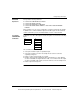
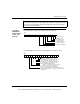
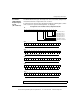
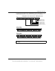
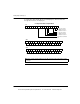
The following figure shows the 4x+2 output register for command 1.
Output 2A Operating Mode
16151413121110987654321
4X+2
Output 2B Operating Mode
Output 1A Operating Mode
Output 1B Operating Mode
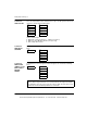
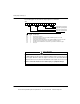
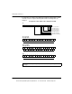
Mode
0
1
2
3
4
5
6
7
Bits
000
001
010
011
100
101
110
111
Description
Disable Output
ON if Count = Setpoint
Latched ON if Count = Setpoint. Hardware RESET required to turn OFF
ON if Count = Maximum Count
Latched ON if Count = Maximum Count. Hardware RESET required to turn OFF
ON when Count = Setpoint for time specified in Command 2 register
ON when Count = Maximum Count for time specified in Command 2 register
Not Used
MODULE DISABLE POSSIBILITY
The Output ON time specified in the Command 2 registers may be used by only one of
the four outputs. When more than one output is set to mode 5 or 6, the module firmware
will operate the first one encountered, and disable the other outputs set to modes 5 or 6.
Failure to follow this instruction can result in injury or equipment damage.
CAUTION
This document provided by Barr-Thorp Electric Co., Inc. 800-473-9123 www.barr-thorp.com