
Hardware reference guide


Intelligent/Special Purpose
35013379 02 October 2007 345
Command 1 -
CONFIGURE,
Output Register
Format (4X =
01XX hex)
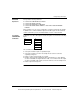
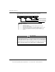
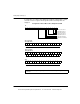
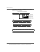
The following figure shows the 4x output register for command 1.
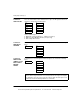
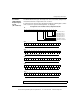
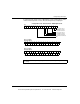
The following figure shows the 4x+1 output register for command 1 (4X+1).
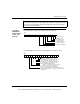
Note: When Command 0 (4X = 00XX) or any other undefined commands are
asserted in the 4X register, the 3X registers will contain the count inputs if in count
mode (same as Command 3) and the rate sample values when in rate-sample
mode (same as Command 4).
16151413121110987654321
4X
1 = Enable Counter 1
1 = Disable Counter 1
1 = Preset Counter 2
1 = Enable Counter 2
1 = Disable Counter 2
Configure Command Bit
1 = Preset Counter 1
16151413121110987654321
4X+1
Two 16 bit counters, Output Assertion ON
0/1 = Pulse/Quadrature Input Counter 1
0/1 = Pulse/Quadrature Input Counter 2
One 32 bit counter, Output Assertion ON
Two 16 bit counters, Output Assertion ON
Two 32 bit counters, Output Assertion OFF
0/1 = Rate Sample Mode OFF/ON
When = 1, automatically sets bits 11 and 12
(i.e., two 32 bit counters, no Output Assert)
0/1 = Comm Lost Output Assert OFF/ON
When = 0, if module communication with the bus is lost,
outputs are disabled. When = 1, outputs continue to operate
as configured.
0
0
1
1
0
1
0
1
This document provided by Barr-Thorp Electric Co., Inc. 800-473-9123 www.barr-thorp.com