
Hardware reference guide

Intelligent/Special Purpose
344
35013379 02 October 2007
Command 2
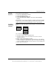
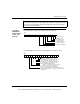
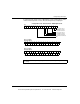
LOAD VALUES
There are four formats for this command. It uses up to six 4X registers and six 3X
registers as shown in the following figure.
Values loaded may be:
z Maximum count and setpoint (i.e., output turn on times).
z Output assertion ON time duration (one input only).
z Rate sample time interval.
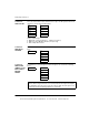
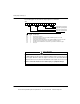
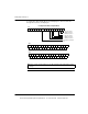
Command 3
READ INPUT
COUNTER
Command 3 uses one 4X register and six 3X registers as shown in the following
figure.
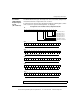
Command 4
READS RATE
SAMPLE or LAST
INPUT COUNT
BEFORE
PRESET
Command 4 uses one 4X register and six 3X registers as shown in the following
figure.
3X
3X+1
3X+2
3X+3
3X+4
3X+5
4X
4X+1
4X+2
4X+3
4X+4
4X+5
3X
3X+1
3X+2
3X+3
3X+4
3X+5
4X
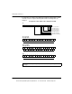
Note: 4X register formats for the commands are described first. The 3X register
contents after issuing Command 1 or 2 are listed after the 4X register description
for Command 2, since the responses are the same for both. The 3X responses for
Commands 3 and 4 immediately follow those commands.
3X
3X+1
3X+2
3X+3
3X+4
3X+5
4X
This document provided by Barr-Thorp Electric Co., Inc. 800-473-9123 www.barr-thorp.com