
Hardware reference guide


Intelligent/Special Purpose
35013379 02 October 2007 343
EHC20200
Operations
Four operations can be performed:
z Command 1 CONFIGURES the Module
z Command 2 LOADS VALUES
z Command 3 READ INPUT COUNTER
z Command 4 READS RATE SAMPLE or LAST INPUT COUNT BEFORE
PRESET
Each operation uses one or more of both types of registers assigned to the module.
In addition to the command definition byte, the first 4X register for all commands
contain control bits to preset and enable/disable counters of either channel.
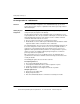
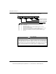
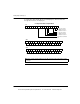
Command 1
CONFIGURES
the Module
Command 1 uses three 4X registers and six 3X registers as shown in the following
figure.
This command does the following:
z Sets up the module for pulse or quadrature input.
z Sets up the module for count or rate-sample mode. Counters cannot be
separately configured.
z Defines counter register length—16 or 32 bit.
z Enables output assertion including module communication loss state. Output
assertion is available if configured for two 16 bit, or one 32 bit counter. No output
assertion is available if two 32 bit counters are defined, or in rate-sample mode.
z Defines output assertion point.
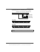
3X
3X+1
3X+2
3X+3
3X+4
3X+5
4X
4X+1
4X+2
This document provided by Barr-Thorp Electric Co., Inc. 800-473-9123 www.barr-thorp.com