
Hardware reference guide


Intelligent/Special Purpose
340
35013379 02 October 2007
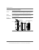
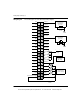
Wiring Diagram The following figure show the EHC10500 wiring diagram.
N/C
2
10
4
6
8
12
14
16
18
20
22
24
26
28
30
32
34
36
38
40 39
37
35
33
31
29
27
25
23
21
19
17
15
13
11
9
7
5
3
1
N/C
N/C
N/C
N/C
M11
M12
M13
M14
M15
IN2
IN4
IN6
IN8
Common Common
OUT2
OUT4
OUT6
OUT8
External Power Supply
Return
OUT7
OUT5
OUT3
OUT1
IN7
IN5
IN3
IN1
24 Vdc C5
24 Vdc C4
24 Vdc C3
24 Vdc C2
24 Vdc C1
5 Vdc C5
5 Vdc C4
5 Vdc C3
5 Vdc C2
5 Vdc C1
5 Vdc Counter
Input Signals
(C1...C5)
5 Vdc
24 Vdc
To M11
To M11
24 Vdc Counter
Input Signals
(C1...C5)
24 Vdc
24 Vdc
Input Signals
(IN1...IN8)
24 Vdc
Output Signals
(OUT1...OUT8)
24 Vdc
+–
+–
+–
+–
This document provided by Barr-Thorp Electric Co., Inc. 800-473-9123 www.barr-thorp.com