
Hardware reference guide


Intelligent/Special Purpose
35013379 02 October 2007 339
LED Indicators
and Descriptions
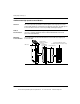
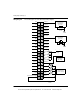
The following figure shows the LED indicators for the EHC10500 high speed
counter.
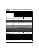
The following table shows the LED descriptions for the EHC10500 high speed
counter.
LED Descriptions
LEDs Color Indication when On
Active Green Bus communication is present
F Red Lights upon any defined hardware, firmware, and
process error.
R Green Indicates firmware initialization is complete and
the module is ready for service.
1 ... 8 (left column) Green Digital inputs IN1 ... IN8
C1 ... C5 Green Counter inputs xxC1 ... xxC5 (xx=5/24)
1 ... 8 (right column) Green Digital outputs OUT1 ... OUT8
P Green 24 Vdc is present
Active F
C11
2
3
4
R
5
6
7
8
1
2
3
4
5
6
7
8
1
C2
C3
C4
C5
P
This document provided by Barr-Thorp Electric Co., Inc. 800-473-9123 www.barr-thorp.com