
Hardware reference guide


Ethernet Modules
35013379 02 October 2007 313
LED Indicators
and Descriptions
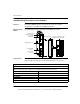
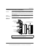
The following figure shows the NOE2X100 LED indicators.
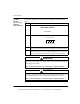
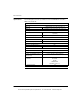
The following table describes the meaning of each NOE2X100 LED indicator.
Installing the
NOE Module
Quantum Ethernet TCP/IP modules come fully configured. However, before
installing your module, you should make sure the default configuration is appropriate
for your network.
If the module will be communicating on an open network, consult your network
administrator to obtain a unique IP network address. You must enter this address in
the Modsoft Ethernet TCP/IP configuration extension screen before installing the
module.
If the module will be communicating on a local network, make sure the default IP
network address is not already in use on that network. To determine the default IP
network address, locate the global address label on the front panel of the module.
Convert the rightmost eight digits from hexadecimal to decimal. The result should be
a decimal number in the form, 84.xxx.xxx.xxx, where each group of xxx is a number
from 0 to 255. This is the default IP network address.
Active
Ready
Run
Kernel
Fault
Coll
Link
Appl
LED Descriptions
LEDs Color Indication when On
Active Green Module is communicating with backplane.
Ready Green Module has passed internal diagnostic tests.
Run Green Flashes during normal operation.
Link Green Ethernet link to hub is ok.
Kernel Amber If steady, module is operating in kernel mode. If flashing, module is waiting for download.
Fault Red An error has been detected, a download has failed or a reset is in process.
Coll Red If steady, cable is not connected. If flashing, Ethernet collisions are occurring.
Appl Amber Entry exists in crash log.
This document provided by Barr-Thorp Electric Co., Inc. 800-473-9123 www.barr-thorp.com