
Hardware reference guide


Modbus Plus NOM
35013379 02 October 2007 303
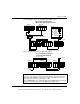
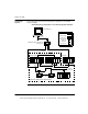
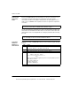
The following figure shows the mixed fiber optic/copper network.
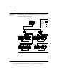
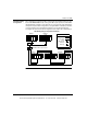
The following figure shows the pure fiber optic network.
Note: The distance between nodes on fiber is limited by the maximum allowable
power loss from end-to-end (3 km over 62.5 mm fiber). Power loss includes the
fiber optic cable attenuation, connector losses at the Fiber Optic Receiver and
Transmitter ports, and the system margin of 3 dB.
The end NOM25200 in this configuration will have the FRNGoff LED active and will
display the Cable B Framing error in the MBPSTAT (in ladder logic).
Node # 1
P/S CPU I/ONOM I/O
211
Node # 2
P/S
CPU
I/O
NOM
I/O
211
490NRP254 Fiber Optic Repeater
Node # 3
P/S
CPU
I/ONOM
I/O
252
Node # 4
P/S
CPU
I/O
NOM
I/O
252
Node # 5
P/S
CPU
I/O
NOM
I/O
252
To Node # n
MB+ Cable
Legend
Fiber Optic
Cable
MB+ Tap with
Terminator
MB+ Tap
(Terminator not
required)
Bus Configuration Example 1
(Mixed Fiber Optic/Copper Network)
Node # 1
P/S CPU I/O
NOM
I/O
252
Node # 2
P/S CPU I/O
NOM
I/O
252
Node # 3
P/S CPU I/ONOM
I/O
252
To Node # n
Fiber Optic Cable
Fiber Optic Cable
To Node # n
Bus Configuration Example 2
(Pure Fiber Optic Network)
This document provided by Barr-Thorp Electric Co., Inc. 800-473-9123 www.barr-thorp.com