
Hardware reference guide

DIO
262
35013379 02 October 2007
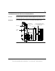
Rear Panel
Switches
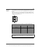
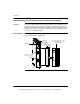
Two rotary switches (refer to the following illustration and table) are located on the
rear panel of the CPU. They are used for setting Modbus Plus node addresses for
the unit.
SW1 (the top switch) sets the upper digit (tens) of the address; SW2 (the bottom
switch) sets the lower digit (ones) of the address. The illustration below shows the
correct setting for an example address of 11.
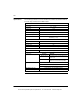
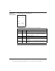
The following table shows the node addresses of the SW1 and SW2 switches.
SW1 and SW2 Switches
Node Address SW1 SW2
1 ... 9 0 1 ... 9
10 ... 19 1 0 ... 9
20 ... 29 2 0 ... 9
30 ... 39 3 0 ... 9
40 ... 49 4 0 ... 9
50 ... 59 5 0 ... 9
60 ... 64 6 0 ... 4
Note: If "0" or an address greater than 32 is selected, the RIO module displays a
flashing Error A and Error B LED to indicate an error condition. Only addresses 1-
32 are valid.
1
3
0
9
2
6
4
5
8
7
1
3
0
9
2
6
4
5
8
7
SW1 (Top)
SW2 (Bottom)
This document provided by Barr-Thorp Electric Co., Inc. 800-473-9123 www.barr-thorp.com