
Hardware reference guide


Quantum Field Bus Modules
35013379 02 October 2007 253
z If not lit, either the LON module requires configuration and mapping or is not
communicating with the CPU by way of the DX Loadable.
z If a LON module is inserted into the backplane and the Ready LED does not
illuminate, the Wink LED should be observed for an error code.
z See the following Wink LED error codes.
Wink LED Error
Codes
The Wink LED is used to display error conditions. The following table shows the
number of times the LED blinks for each type of error.
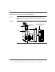
Front Panel Push
Buttons
Two push buttons are located on the front of the NOL module. The service pin push
button initiates the LonWorks network installation. When depressed, it causes the
Service LED to illuminate, and forces the Neuron Chip in the module to output its
unique 48-bit ID and Program ID.
The reset push button performs a hardware reset of the module, and must be done
each time new firmware has been downloaded.
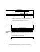
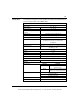
MSG Out Green Off Off Blink N/A
Wink Green Off Off Blink on
command
Blink
3
Srvc Yellow Off Blink Off N/A
LED Indicator Status
LED Color Condition of NOL Module Error Condition
Powered Up
Not Configured
Not Programmed
Powered Up
Configured
Not
Programmed
Normal
Operation
Configured
Programmed
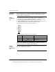
LED Error Codes
Number of Blinks Error Condition
1 Module is in the bootloader
2 Error in writing to flash memory
3 Error in initializing the Lon Works network
4 Error in the module configuration
Note: The Reset push-button is recessed and requires a paper clip or similar tool
to activate.
This document provided by Barr-Thorp Electric Co., Inc. 800-473-9123 www.barr-thorp.com