
Hardware reference guide


Quantum Field Bus Modules
35013379 02 October 2007 247
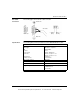
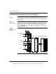
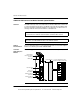
InterBus Port Connect the remote bus cable to the female connector port labeled interbus. The
following figure shows the InterBus port connection.
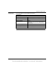
The following table shows the key to the remote bus.
Pin Signal Function
1 DO Data Out (+)
2 DI Data In (+)
3 GND Comm
4 GND (NOA622 only) F/O Interface
5 VCC (NOA622 only) F/O Interface
6 DO Data Out (-)
7 DI Data In (-)
8 VCC (NOA622 only) Auxiliary Supply for F/O
Interface
9 RBST (NOA622 only) RBST Coupling
Black circle = Pin occupied. White circle = N/C
INTERBUS
remote bus
This document provided by Barr-Thorp Electric Co., Inc. 800-473-9123 www.barr-thorp.com