
Hardware reference guide

Quantum Field Bus Modules
35013379 02 October 2007 239
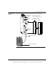
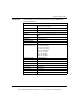
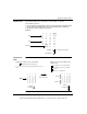
LED Bus Mode Each indicator lamp 1-31 corresponds to a slave address on the bus.
z On: Slave is present.
z Flashing: Slave is mapped but not detected, or detected but not mapped. It may
also be projected and detected, but not activated (bad profile or I/O code).
z Off: Slave is neither mapped nor detected.
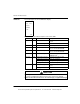
Example:
LED Slave I/O
Mode
Slave mode (SLV) figure:
On
0 8 16 24
1 9 17 25
210 18 26
311 19 27
412 20 28
513 21 29
614 22 30
715 23 31
Off
Flashing
SLV/BUS
I/O STATUS
Select with mode pushbutton
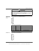
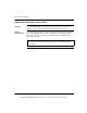
Display of the address of the selected slave:
08724
19025
2101826
3 11 19 27
4122028
5132129
6142230
7152331
SLV/BUS
I/O STATUS
On: number of the selected slave
A short press on the address button will change the selected
slave.
Slave 3
selected
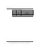
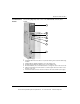
Display of the state of the I/O bits of the
0 81624
1 91725
2 10 18 26
3 11 19 27
4 12 20 28
5 13 21 29
6 14 22 30
7 15 23 31
SLV/BUS
I/O STATUS
0-3: displays the state of the input bits
selected slave:
4-7: displays the state of the output bits
On: bit = 1
Off: bit = 0 or not significant
Long press on the
address push button
{
{
Input bits
Output bits
This document provided by Barr-Thorp Electric Co., Inc. 800-473-9123 www.barr-thorp.com