
Hardware reference guide

Quantum Field Bus Modules
35013379 02 October 2007 237
Communications
Module
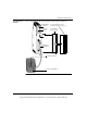
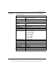
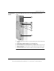
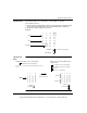
The following diagram provides a view of the 140EIA92100 communications
module.
1 LED Display
2 AS-i (Red): ON shows the module is not powered. Flashing shows automatic addressing
enabled.
3 SLV/BUS (Green): ON when LEDs 0-31 are in bus display mode.
4 I/O Status (Green): ON when LEDs 0-31 are in slave display mode.
5 Mode (Push Button): Press and hold this button to change from slave mode to bus mode.
6 Address (Push Button): Press this button to scroll through the 32 slaves. Hold to reverse
direction of the scroll.
7 AS-i Channel Cable Connector: Connects module to AS-i cable and AS-i power supply.
1
2
3
4
5
6
7
This document provided by Barr-Thorp Electric Co., Inc. 800-473-9123 www.barr-thorp.com