
Hardware reference guide


CPU Modules
35013379 02 October 2007 225
Rear Panel
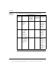
Switches
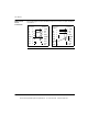
The following figure shows the SW1 and SW2 settings.
SW1 sets the upper digit (tens) of the address. SW2 sets the lower digit (ones) of
the address. The following table shows the SW1 and SW2 address settings.
Modbus
Connector
Pinouts
All Quantum CPUs are equipped with a nine-pin RS-232 connector that support
Modicon’s proprietary Modbus communication protocol. The following is the Modbus
port pinout connections for nine-pin and 25-pin connections.
Modbus Port
Modem Support
Modbus Port 1 has full modem interfacing ability. Modbus Port 2 RTS/CTS
connections function properly for normal non-modem communications but do not
support modems.
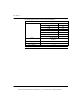
SW1 and SW2 Address Settings
Node Address SW1 SW2
1 ... 9 0 1 ... 9
10 ... 19 1 0 ... 9
20 ... 29 2 0 ... 9
30 ... 39 3 0 ... 9
40 ... 49 4 0 ... 9
50 ... 59 5 0 ... 9
60 ... 64 6 0 ... 4
Note: If "0" or an address greater than 64 is selected, the Modbus + LED will be
"on" steady, to indicate the selection of an invalid address.
1
3
0
9
2
6
4
5
8
7
1
3
0
9
2
6
4
5
8
7
SW1 (TOP)
SW2 (BOTTOM)
Note: Although the Modbus ports electrically support existing Modbus cables, it is
recommended that a Modbus programming cable (Part # 990NAA26320 or
990NAA26350) be used. This cable has been designed to fit under the door of a
Quantum CPU or NOM module.
This document provided by Barr-Thorp Electric Co., Inc. 800-473-9123 www.barr-thorp.com