
Hardware reference guide


CPU Modules
200
35013379 02 October 2007
140CPU53414A CPU Module
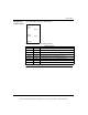
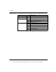
Overview This unit provides information on the specifications, LED indicators and description
and error codes for the 140CPU53414A Controller Module.
This module is functionally identical to the non-"A" version, however, the following
should be considered:
z If you are using the module in a Hot Standby topology, then you must use either
two non-"A" models or two "A" models.
z The "A" version requires a new flash executive.
z The "A" version and non-"A" flash executives are not interchangeable.
z Schneider Automation software (Concept, ProWORX, and Modsoft) supports the
"A" version. Any existing or new 140CPU53414 program configuration will load
into a 140CPU53414A without any modifications.
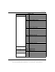
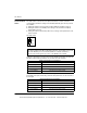
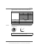
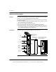
CPU Module The following figure shows the CPU Module and its components.
Modbus
Comm 1
Date
Installed
Batt.
Modbus
Comm 1
Network
Node
Customer Identification Label
(Fold label and place it inside
door) Part #31002249
Removable door
Part #043513804
Model Number
Module Description
Color Code
LED
Area
Battery
Key Switch
Modbus
Connector
140
CPU 534 14A
586 CONTROLLER
Modbus
Connector
Modbus Plus
Connector
Modbus
Comm 2
Modbus
Plus
Slide
Switch
Modbus
Plus
ASCII
RTU
mem
X
Modbus
Comm 2
This document provided by Barr-Thorp Electric Co., Inc. 800-473-9123 www.barr-thorp.com