
Hardware reference guide

CPU Modules
184
35013379 02 October 2007
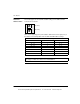
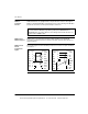
Rear Panel
Address Switch
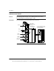
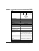
The following figure shows the SW1 and SW2 settings for the Address Switch
located on the rear panel.
SW1 sets the upper digit (tens) of the address. SW2 sets the lower digit (ones) of
the address. The following table shows the SW1 and SW2 address settings.
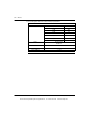
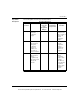
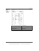
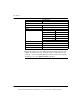
SW1 and SW2 Address Settings
Node Address SW1 SW2
1 ... 9 0 1 ... 9
10 ... 19 1 0 ... 9
20 ... 29 2 0 ... 9
30 ... 39 3 0 ... 9
40 ... 49 4 0 ... 9
50 ... 59 5 0 ... 9
60 ... 64 6 0 ... 4
Note: If "0" or an address greater than 64 is selected, the Modbus + LED will be
"on" steady, to indicate the selection of an invalid address.
1
3
0
9
2
6
4
5
8
7
1
3
0
9
2
6
4
5
8
7
SW1 (TENS)
SW2 (ONES)
This document provided by Barr-Thorp Electric Co., Inc. 800-473-9123 www.barr-thorp.com