
Hardware reference guide

CPU Modules
35013379 02 October 2007 145
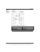
Front Panel
Switches
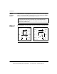
Two, three-position slide switches are located on the front of the CPU. The left
switch is used for memory protection when in the top position and no memory
protection in the middle and bottom positions. The three-position slide switch on the
right is used to select the communication parameter settings for the Modbus
(RS-232) ports.
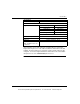
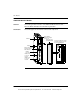
The following figure shows the three options that are available.
Setting the slide switch to the top position assigns ASCII functionality to the port; the
following communication parameters are set and cannot be changed
Setting the slide switch to the middle position assigns remote terminal unit (RTU)
functionality to the port; the following communication parameters are set and cannot
be changed.
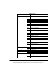
Setting the slide switch to the bottom position gives you the ability to assign
communication parameters to the port in software; the following parameters are
valid.
Note: The CPU hardware defaults to bridge mode when the front panel switch is
set to RTU or ASCII mode. When networking controllers, a panel device connected
to the CPU Modbus port can communicationunicate with the controller to which it
is connected, as well as log into any nodes on the Modbus Plus network.
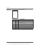
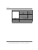
ASCII Communication Port Parameters
Baud 2,400
Parity Even
Data Bits 7
Stop Bits 1
Device Address Rear panel rotary switch setting
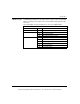
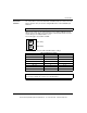
RTU Communication Port Parameters
Baud 9,600
Parity Even
Data Bits 8
Stop Bits 1
Device Address Rear panel rotary switch setting
ASCII
RTU
memnot used
off
mem
prt
This document provided by Barr-Thorp Electric Co., Inc. 800-473-9123 www.barr-thorp.com