
Hardware reference guide
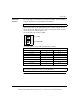

CPU Modules
35013379 02 October 2007 125
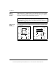
Rear Panel
Switches
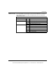
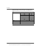
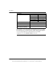
Two rotary switches are located on the rear panel of the CPU. They are used for
setting the Modbus Plus node and Modbus port addresses.
SW1 (the top switch) sets the upper digit (tens) of the address; SW2 (the bottom
switch) sets the lower digit (ones) of the address. The illustration below shows the
correct setting for an example address of 11.
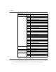
The following figure shows SW1 and SW2.
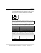
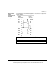
The following table shows the SW1 and SW2 address settings.
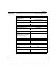
Note: The highest address that may be set with these switches is 64.
SW1 and SW2 Address Settings
Node Address SW1 SW2
1 ... 9 0 1 ... 9
10 ... 19 1 0 ... 9
20 ... 29 2 0 ... 9
30 ... 39 3 0 ... 9
40 ... 49 4 0 ... 9
50 ... 59 5 0 ... 9
60 ... 64 6 0 ... 4
Note: If "0" or an address greater than 64 is selected, the Modbus + LED will be
"on" steady, to indicate the selection of an invalid address.
1
3
0
9
2
6
4
5
8
7
1
3
0
9
2
6
4
5
8
7
SW 1 (TOP)
SW 2 (BOTTOM)
This document provided by Barr-Thorp Electric Co., Inc. 800-473-9123 www.barr-thorp.com