
Hardware reference guide

Power Supplies
35013379 02 October 2007 107
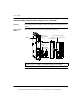
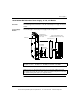
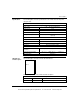
Wiring Diagram The following figure shows the CPS42400 wiring diagram.
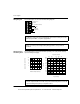
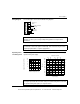
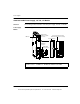
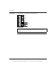
Operating Curve
and Timing Chart
The following figures show the CPS42400 operating curve (left) and the hold-up
capacitor timing chart (right).
Note: See Power and Grounding Considerations for AC and DC Powered
Systems, p. 776 for power and grounding wiring guidelines and operational
information.
Note: A normally closed relay contact rated at 220 Vac, 6A / 30 Vdc, 5A is available
on terminals 1 and 2 of the power terminal strip. This contact set may be used to
signal input power OFF, or a power supply failure.
}
1
2
3
4
5
6
7
Power Loss
Alarm
-48 ... -60 Vdc (Common)
+48 ... +60 Vdc
+
-
Capacitor
(Optional)
Note: Tolerance to input interruptions may be increased by adding a ≥ 80 Vdc
electrolytic capacitor between 5 and 6 of the power terminal strip. Refer to the hold-
up capacitor timing chart (above) for capacitor values.
Capacitor size/mF
Input Voltage
Time/ms
100
90
80
70
60
50
40
30
20
10
0
40
45 50 55 60 65 70
2.2
1
0
47 22 10 6.8 4.7
Ambient Temperature (C)
Output to Bus CurrentT (A)
40
60
50 55
45
12
10
8
6
4
2
This document provided by Barr-Thorp Electric Co., Inc. 800-473-9123 www.barr-thorp.com