
User's Manual
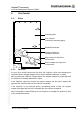
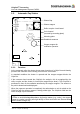
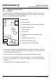
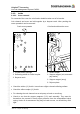
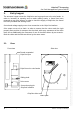
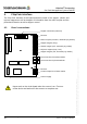
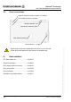
Table Of Contents

ChipCoin
®
Processing
Car Park Management System PMS20
ChipCoin Processing Manual
4. ChipCoin interface
The Chip-Coin interface circuit board assumes control of the stopper, shutter and
rejector magnets as well as analysis of information from the reflex coupler and the
photoelectric barrier as well as hopper control.
4.1. View / connections
10 Article no. of chapter: 86 93538 (d)
© 2004 by Scheidt & Bachmann GmbH, Mönchengladbach (Germany)
All rights reserverd. Subject to alterations. Some Illustrations and descriptions may also include special options.
Reserve
Reflex coupler (entrance, automatic pay station)
Stopper magnet (entry)
Shutter magnet (exit, automatic pay station)
Rejector magnet (entry / exit)
Stopper magnet (exit, automatic pay station)
LW connection for luminous diode
LW connection for phototransistor
Reserve
Current output for PIT base station
Hopper connection (entrance)
Current supply
Never work on the circuit board when the current is on. First turn
off the device and wait until it has come to a complete rest.