
User manual

Operating and Installation Instructions for Battery Booster WA 1208
3
Date: 22.06.2010
820.508 BAMA / EN
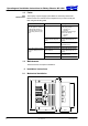
³ Install in a dry, sufficiently ventilated location.
³ Ensure a minimum clearance to the surrounding fixtures and fittings:
F
Maintain a gap of at least 5cm on all sides (except mounted side).
F
Ensure cables are routed properly.
F
The ambient temperature may not exceed +40 °C during operation.
Y
ATTENTION!
There is a risk of overheating when the required gaps are not adhered to or
when ventilation slits are covered.
Firmly screw the booster into place:
³ Secure the booster with two screws (diameter 3 mm) on an even surface
(any installation position).
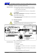
2.2 Electrical connection
Y
ATTENTION!
To prevent damage in the event of a fault, fuses must be inserted as in Fig.
2 depending on the cable cable cross-section (EN 1648-1 and 2).
9
10
13
11
15A
15A
2A
15A
+
--
Input
+
--
Output
Charging ”ON”
WA 1208
+
--
Refrigerator
Battery
Relay circuit ”+ Refrigerator” (connector no. 10)
From terminal 15 (voltage for igni tion ”ON”)
+
--
+
--
Towing vehicle Caravan
Assignment of the 13-pin
socket to EN
1648-1:
9 + Charging line
10 + Refrigerator (charging ”ON”)
13 -- Charging line
11 -- Refrigerator
Fig. 2 Block diagram of LT 226 connection
Required for the connection:
F
2 fuse holders
F
1 x 2A fuse, 1 x 15A fuse
F
Insulated flat push-on contacts, 6.3 mm red (0.3...1.5 mm
2
) and blue
(1.0...2.5 mm
2
)
F
Add-on relay in the towing vehicle if necessary (accessory, Schaudt
part no. 922.050)
F
Cable (recommended: 0.75 mm
2
and 2.5 mm
2
)
Environment
Minimum clearance
Fitting
Connection material