
Datasheet
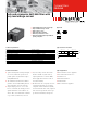

> Components > FN 2450
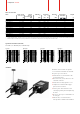
Per CISPR 17; A = 50Ω/50Ω sym; B = 50Ω/50Ω asym
Typical filter attenuation (FN 2450F)
6A types 10A types
16A types
20A types
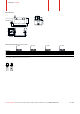
* The letter following FN 2450_ represents the value of the Y-capacitor and is directly related to the performance and leakage current of the filter. Other Y-capacitor values are available upon request.
** Maximum leakage current under normal operating conditions. Note: if the neutral line is interrupted, worst case leakage could reach twice this level.
Filter* Rated current Leakage Inductance Capacitance Resistance Input/Output Weight
@ 55°C (40°C) current** L Cx Cy R connections
@ 230VAC/50Hz
[A] [mA] [mH] [μF] [nF] [MΩ] [g]
Filter selection table
FN 2450G-6-61 6 (6.8) 0.73 10.5 0.47 4.7 1 -61 210
FN 2450G-10-61 10 (11.4) 0.73 4.9 0.47 4.7 1 -61 210
FN 2450G-16-61 16 (18.2) 0.73 1.84 0.47 4.7 1 -61 210
FN 2450G-20-61 20 (22.8) 0.73 0.94 0.47 4.7 1 -61 210
FN 2450F-6-61 6 (6.8) 0.52 10.5 0.47 3.3 1 -61 210
FN 2450F-10-61 10 (11.4) 0.52 4.9 0.47 3.3 1 -61 210
FN 2450F-16-61 16 (18.2) 0.52 1.84 0.47 3.3 1 -61 210
FN 2450F-20-61 20 (22.8) 0.52 0.94 0.47 3.3 1 -61 210
FN 2450B-6-61 6 (6.8) 0.002 10.5 0.47 1 -61 210
FN 2450B-10-61 10 (11.4) 0.002 4.9 0.47 1 -61 210
FN 2450B-16-61 16 (18.2) 0.002 1.84 0.47 1 -61 210
FN 2450B-20-61 20 (22.8) 0.002 0.94 0.47 1 -61 210
FN 2450 are delivered with closed plastic
covers and fastened terminals. To install the
filter please proceed as follows:
n Mount the filter on a metal surface with
two appropriate bolts.
n First connect the green/yellow wire to the
earth stud of the filter.
n Gently lift the two hinged plastic covers.
n Untighten the terminals with an appro-
priately sized screw driver.
n Connect phase and neutral wires with
cable lugs by pushing down and tightening
the bolts.
n Please note the torque recommendation on
the next page.
n Push the safety covers back into their
locked position to finish the filter installaton.
Installation