
User Manual


WATER SUPPLY SYSTEM continued
A drain in the reservoir allows you to drain the unit for cleaning and maintenance. A drain cap on the underside of the aluminum tray covers the drain
during operation. Make sure the cap is in place before you fill the reservoir. The drain cap should be finger-tightened only.
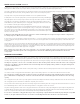
The pump is attached to a bracket, which in turn is fixed to the blower housing. The bracket holds the pump in its proper position on top of the foam
filter and slightly above the bottom, allowing sufficient space for water to enter the pump suction.
The pump can be easily removed and replaced with the services of a qualified electrician.
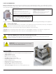
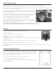
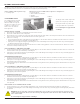
A small plastic screen covers the pump inlet to prevent foreign matter from entering and damaging
the pump impeller. The screen snaps in place and can be easily removed for inspection or cleaning.
The pump sits on a foam filter; somewhat like a sponge. The filter traps dirt that could enter the
water distribution system and build up on the cooling pads, reducing their effectiveness. Dirt could
also accumulate in the PVC pipes and plug the spray holes.
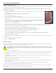
The pump discharges through a fine screen washable filter which decreases the contamination of
the cooling pads and water system. The discharge filter casing is a clear plastic so dirt buildup on
the internal screen is easily visible. As dirt builds up, water flow to the cooling pads is reduced and
performance decreases. The clear filter housing is threaded and screws into the filter body for easy
removal to access the screen.
A dirty water supply will quickly reduce the unit's performance and the unit will require more frequent cleaning to maintain cooling effective-
ness. Always try to use a filtered, treated water supply.
A clear vinyl hose connects the pump to the filter. From the filter, a "T" connector supplies two lines that run along the bottom and up opposite frame
|corners to supply the PVC pipe with water. Each vinyl hose connects to two PVC pipes which run horizontally along the top of the frame above the
cooling pads.
The PVC pipes have a series of holes that run the full length of the pipe. Each PVC pipe is covered with a plastic mesh sock which helps break up the
water as it leaves the spray holes. This gives a more even water distribution across the cooling pad and reduces splashing. The holes direct the water
inward at a 90° angle to continuously saturate the cooling pads from the top down. Excess water drains back to the reservoir through drainage holes
in the bottom support channels which support the cooling pads.
Water cleanliness has a major effect on the cooler's performance. Use a clean water supply and consider a water softener if your water is hard.
Dissolved solids in hard water deposit on the cooling pad surfaces and reduce the airflow through the unit and therefore the amount
of evaporation.
COOLING PAD ASSEMBLY
The cooling pads are critical for proper, efficient cooler operation. They are made of laminated cellulose (paper) fibers and arranged to give a large
surface area for evaporation and to provide a rigid structure. The shape of the cells allows high velocity airflow through the pad at a minimum pres-
sure drop. At the same time, the air passages between the cells force the incoming air to impinge on the wet cell surfaces and maximize evaporation.
The WayCool evaporative cooler also acts as an air filter and removes dust and other particles from the air. This dirt collects on the cooling pads
and lowers cooler efficiency. The pads should be cleaned at least weekly and more frequently in dusty conditions. See Regular Cleaning under
"Operation and Maintenance."
The pump supplies a continuous flow of water over the pads causing a "sheet flow" which constantly replaces the water lost to evaporation and keeps
the pads saturated.
One cubic foot of the cooling pad material holds about a gallon of water during operation. One cubic meter holds about 100 liters of water.
The cooling pads are relatively strong but are subject to crushing, especially when wet. Always run the unit with the plastic retaining grates in
place and handle them carefully when you clean them. Crushed cells reduce the total airflow through the unit and therefore lowers its cooling
capacity.
The cooling pad sections (two sections per side, eight sections total) are held by metal channels at the top and bottom of the unit. The channels hold
the cooling pads in position and form four sidewalls to completely enclose the unit.
The top channels house the PVC pipe, which run horizontally along the channel directly above the cooling pads. The bottom channels have a series of
holes drilled through them to allow excess water flowing down the cooling pads to return to the reservoir.
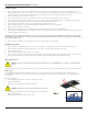
The plastic retaining grates fit in front of the cooling pads and sit in the same channels as the pads; holding them in place and protecting them from
accidental damage. The plastic grates and cooling pads are easily removed by placing a flat blade under the bottom and lifting upwards, then out-
wards. Once one pad is removed, the others can be lifted up and out by hand without using a blade.
Do not remove or handle the cooling pads when they are wet, as they damage easily. Run the blower without the pump until pads are dry. With
normal care, the pads should last at least two seasons. Abuse or mishandling will reduce their effectiveness and shorten their life.
Plastic Plastic
screenscreen
Pump Pump
ImpellerImpeller
PumpPump
©2020 Schaefer®. All Rights Reserved. Portable Evaporative Cooler Operators Manual5