
User manual

11
ENGLISH
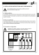
6. INSTALLATION INSTRUCTIONS AND CONFIGURATION
6.1 Wall installation
For installation on the wall, the four housing screws must be removed from the cover. After-
wards, the front plate must be lifted - if necessary - the ribbon cable must be removed from
the electrical outlet. The subshell of the device can now be installed on the wall (assembly
material is included).
6.2 Sensor installation
The sensor reacts to water contact at the two metal contacts (the sensor circuit is closed).
The assembly height of the sensor denes, at what level the water detector will sound an
alarm. The sensor cable can be lengthened up to a 50-meter dual-wire cable, and ve water
sensors can be connected per input in parallel.
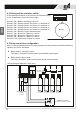
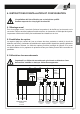
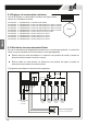
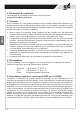
6.3 Connection conguration
Important! The cables running to the water detector must be
surface-mounted and installed in a xed, solid maner!
L
L
N
N
PE
PE
S
G
Ö
Relay plug-in card
connection
Operating voltage
230 V AC
50-60 Hz
Sensor 1
Float switch
Sensor 2
Float switch
Sensor 3
Float switch
Sensor 4
Float switch
L N
PE
Relay
8A/230V
Option:
9V battery
The installation shall be performed by qualied personnel.
Please note the ve safety rules!