USB 3.0 SK1024U3PD Monochrome Line Scan Camera 1024 pixels, 10 µm x 10 µm, 50 / 25 MHz pixel frequency • Robust cable connections • Hot-pluggable • Perfect for movable setups Instruction Manual Schäfter + Kirchhoff © 2014 • Line Scan Camera SK1024U3PD Manual (05.2014) • shared_Titel_AT1.indd (05.2014) 05.
Contents Contents...................................................................................................................................................................... 2 1. 2. 3. Schäfter + Kirchhoff © 2014 • Line Scan Camera SK1024U3PD Manual (05.2014) • shared_Contens.indd (05.2014) 4. 5. Introducing the SK1024U3PD Line Scan Camera with USB 3.0 Interface..................................................... 3 1.1 Intended Purpose and Overview.......................................
1. Introducing the SK1024U3PD Line Scan Camera with USB 3.0 Interface 1. Introducing the SK1024U3PD Line Scan Camera with USB 3.0 Interface 1.1 Intended Purpose and Overview The SK line scan camera series is designed for both wide range of vision and inspection applications in industrial and scientific environments. The SK1024U3PD is ideally suited for portability. The robustly attached dedicated connections enable external synchronization of the camera and the output of data to the USB 3.
1. Introducing the Line Scan Camera with USB 3.0 Interface 1.3 Computer System Requirements • Intel Pentium Dual Core or AMD equivalent • RAM min. 4 GB, depending on size of acquired images • USB 3.0 interface. With a USB 2.0 interface the camera can be used at reduced line frequency. • High-performance video card, PCIe bus • Operating System Windows 7 (64- or 32-bit), Windows XP (Service Pack 3) • Compact disk drive for software installation. 1.
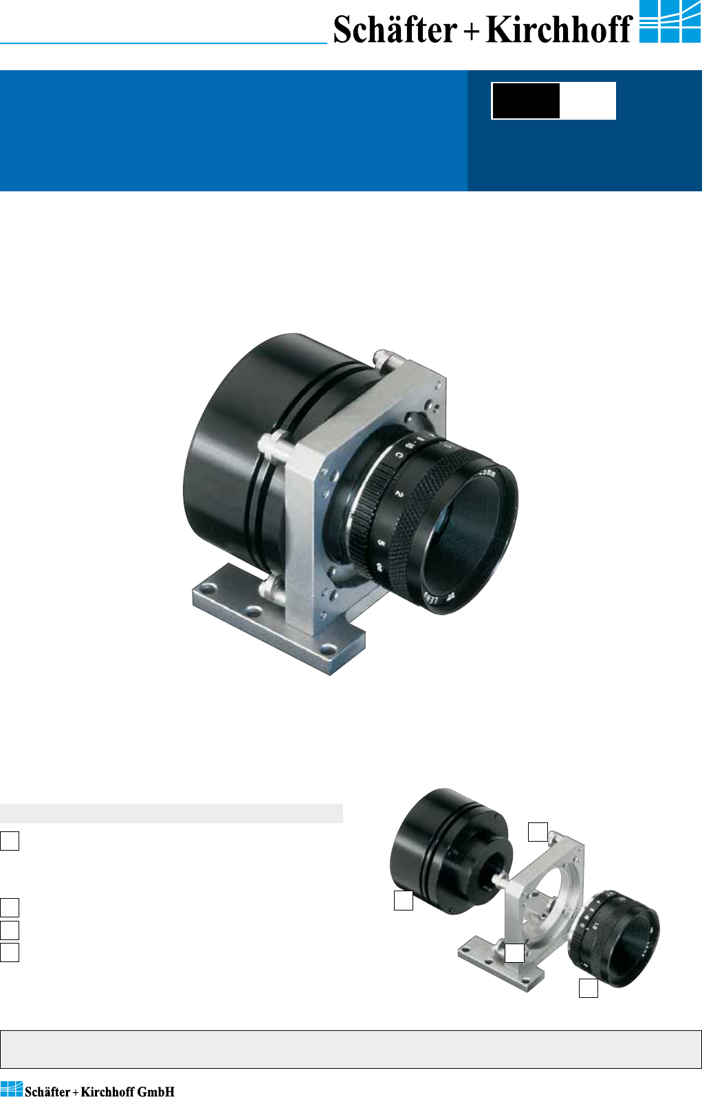
2. Installation and Setup 2. Installation and Setup 2.1 Mechanical Installation: Mounting Options and Dimensions Mounting Options Optics Handling • The best fixing point of the camera is the seat for the mounting bracket SK5105, which is available as an accessory. • • Four threaded holes M3 x 6.5 mm provide further options for customized brackets. If the camera and the optics are ordered as a kit, the components are pre-assembled and shipped as one unit.
2. Installation and Setup 2.2 Electrical Installation: Connections and I/O Signals • The USB 3.0 interface provides data transfer, camera control and power supply capabilities to the SK1024U3PD line scan camera. If you want to operate the camera in Free Run (SK Mode 0) trigger mode the USB 3.0 cable is the only connection you have to make. • For any kind of synchronized operation, the external trigger signal(s) have to be wired to socket 2 .
2. Installation and Setup 2.3 Software Installation • The PC hardware requirements are listed in section 1.3 Computer System Requirements, p. 4 • See section 2.2 Electrical Installation: Connections and I/O Signals, p. 6. prior to software installation. • This section focusses on driver installation and initial operation of the camera. For a comprehensive description of the software package, see the separate SK91USB3-WIN software manual. a few seconds.
3. Camera Control and Performing a Scan 3. Camera Control and Performing a Scan 3.1 Software: SkLineScan • Start the SkLineScan program. • The most common functions of the line scan camera can be controlled by dialog boxes. • Commands for comprehensive camera functionality can be entered in the "Camera Gain / Offset Control" dialog. • For a guide on how to carry out imaging and how to work with the obtained data with the Schäfter + Kirchhoff software package, see the SK91USB3-WIN software manual.
3. Camera Control and Performing a Scan Basic Visualization of the Sensor Output Signal Window / Oscilloscope Display The signal window plots the digitalized brightness profile as signal intensity (y-axis) versus the sensor length (x-axis) at a high refresh rate. The scaling of the y-axis depends on the resolution of the A/D converter: The scale range is from 0 to 255 for 8-bits and from 0 to 4095 for 12-bits. The scaling of the x-axis corresponds with the number of pixels in the line sensor.
3. Camera Control and Performing a Scan 3.
3. Camera Control and Performing a Scan Sensor Alignment If you are operating with a linear illumination source, check the alignment of the illumination source and the sensor prior to a shading correction, as rotating the line sensor results in asymmetric vignetting. Sensor and optics aligned Sensor and optics rotated in apposition Gain/Offset Control Dialog Cameras are shipped prealigned with gain/offset factory settings.
3. Camera Control and Performing a Scan Shading Correction Shading Correction compensates for non-uniform illumination, lens vignetting as well as any differences in pixel sensitivity. The signal from a white homogeneous background is obtained and used as a reference to correct each pixel of the sensor with an individual factor, scaled up to the intensity maximum (255 at 8-bit resolution and 4095 at 12-bit) to provide a flat signal.
3. Camera Control and Performing a Scan Shading Correction Memories and API Functions As an alternative to the user dialog, a new shading correction reference signal can also be created by using application programming interface (API) functions. The relationshhip between the storage locations and the related API functions are shown in the diagram below. The API functions are included in the SK91USB3-WIN software package. See the SK91USB3-WIN manual for details.
3. Camera Control and Performing a Scan Synchronization of the Imaging Procedure and the Object Scan Velocity • A two-dimensional image is generated by moving either the object or the camera. The direction of the translation movement must be orthogonal to the sensor axis of the CCD line scan camera. • To obtain a proportional image with the correct aspect ratio, a line synchronous transport with the laterally correct pixel assignment is required.
3. Camera Control and Performing a Scan The synchronization mode determines the timing of the line scan. Synchronization can be either performed internally or triggered by an external source, e.g. an encoder signal. The line scan camera can be externally triggered in two different ways: 1. 2. Line-triggered synchronization: Each single line scan is triggered by the falling edge of a TTL signal supplied to LINE SYNC A input.
4. Advanced SkLineScan Software Functions 4. Advanced SkLineScan Software Functions 4.1 Camera Control by Commands In addition to user dialog inputs, the SkLineScan software also provides the option to adjust any camera settings, such as gain, offset, trigger modes, by sending control commands directly. Similarly, current parameters, as well as specific product information, can be read from the camera using the request commands. All set and request commands are listed in the tables below.
4. Advanced SkLineScan Software Functions Request Commands Set Operation Description Request Return Goooo Boooo even gain setting (channel A) 0-24 dB odd gain setting (channel B) 0-24 dB Oppp Pppp even offset setting (channel A) odd offset setting (channel B) K R S I SK1024U3PD Rev1.08 SNr00163 SK1024U3PD Rev1.
4. Advanced SkLineScan Software Functions 4.2 Advanced Synchronization Control The basic synchronization function makes use of the trigger input LINE SYNC A. The trigger mode is determined by the settings in the "Camera Control" dialog, e.g. LineStart (1) or ExposureStart (4). Advanced trigger functions are provided by combining LINE SYNC A with a second trigger input LINE SYNC B. The operation mode is controlled by the entries in the Sync Control Register (SCR).
4. Advanced SkLineScan Software Functions Example Timing Diagrams of Advanced Synchronization Control Annotations: SyncA SyncB Count Trigger = = = = LINE SYNC A (external line synchronization input, I/O connector) LINE SYNC B (external line synchronization input, I/O connector) internal counter Generated trigger pulses from the Trigger Control stage. The signal goes to the Trigger Divider stage inside the camera.
5. 5. Sensor Information Sensor Information Manufacturer: DALSA Corp. Type: IL-P1-1024 Data source: DALSA Line Scan Sensors, Document 03-036-00134-05 Pin Functional Description Schäfter + Kirchhoff © 2014 • Line Scan Camera SK1024U3PD Manual (05.2014) • shared_Sensor_IL-P1.indd (05.
Schäfter + Kirchhoff © 2014 • Line Scan Camera SK1024U3PD Manual (05.2014) • shared_Sensor_IL-P1.indd (05.2014) 5.
Glossary Exposure period Shading correction is the illumination cycle of a line scan sensor. It is the integration time plus the additional time to complete the read-out of the accumulated charges and the output procedure. While the charges from a finished line scan are being read out, the next line scan is b eing exposed. The exposure period is a function of the pixel number and the pixel frequency.
CE-Conformity Warranty This manual has been prepared and reviewed as carefully as possible but no warranty is given or implied for any errors of fact or in interpretation that may arise. If an error is suspected then the reader is kindly requested to inform us for appropriate action. The circuits, descriptions and tables may be subject to and are not meant to infringe upon the rights of a third party and are provided for informational purposes only.
Accessories and Spare Parts Mounting bracket SK5105 Order Code Warp-resistant construction for mounting the line scan camera Clamp set SK5102 Order Code to lock the line scan camera in a desired position (set of 4) Mounting console SK5105-2 Order Code for indirect mounting of the line scan camera via the extension tube, suitable for an extension tube larger than 50 mm, for example with a macro lens. USB 3.0 cable SK9020.3 Camera connector: USB 3.