
User guide

12 CATx KVM Extender Local Hubs
2. Installation
For first-time users, we recommend that you carry out a test placement,
confined to a single room, before commencing full installation. This will allow
you to identify and solve any cabling problems, and experiment with the KVM
extender system more conveniently.
Package Contents
You should receive the following items in your extender package. If anything is
missing, please refer to Appendix C: Obtaining Technical Support, page 37.
• KVM Extender Local Hub Unit.
• 5V DC PSU and power cable.
• Quick Start Guide.
Interconnection Cable Requirements
To connect the Local and Remote Units you will need CATx (any category 5,
5e, 6 or higher) cable terminated with RJ45 plugs. Please note that shielded
cable is advised to maintain regulatory EMC compliance.
Interconnect cables must be solid-core type. Stranded patch cable will give poor
results over longer distances. The pairing of the cable and pinning of its
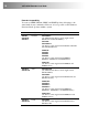
connectors should normally be in accordance with EIA-568B. The following
table illustrates which RJ45 connector pins the extenders use for various
signals. It also details the standard EIA-568B wiring scheme that is
recommended for most installations.
Looking into the RJ45 socket, Pin 1 is on the right and Pin 8 on the left.
Pin Color (EIA-568B) Signal
1
2
White/Orange
Orange/White
Blue Video
3
6
White/Green
Green/White
Green Video
4
5
Blue/White
White/Blue
Red Video
7
8
White/Brown
Brown/White
Data
EIA-568A wiring can also be used. Contact Technical Support for details.
With some cables, video performance may be improved by using a cross-over
patch cable at each end or an alternative RJ45 pin-out.