Intelligent TFT-LCD Module Model STVI104WT-01 Equipment Manual STVI104WT-01 Equipment Manual Release 04/2016
Contents Preface ..................................................................................................................................... 3 1 Introduction ...................................................................................................................... 5 2 Technical Parameters ................................................................................................ 10 3 Interface Description ......................................................................
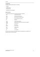
Preface This equipment manual is part of our Intelligent TFT-LCD Module documentation. It provides the information in regards of operation, installation, configuration, function, system as well as its technical design and working principle.
Preface Trademarks STONE registered trademarks are as below: - STONE - STONE TECH - Intelligent HMI - Intelligent TFT-LCD Module Abbreviations The abbreviation table in this equipment manual is as below: LED Light Emitting Diode CPU Central Processing Unit ESD Electrostatic Sensitive Device HMI Human Machine Interface IF Interface LCD Liquid Crystal Display UART Universal Asynchronous Receiver/Transmitter COM Commercial DIN Data Input DOUT Data Output VIN Voltage Input GND Ground T
1Introduction This chapter contains general information of: - Brief Introduction - Warranty - Product Characteristics - Application Area - Working principle - Operation Processing - Software Operation STVI104WT-01 Equipment Manual Release 04/2016 -5-
Introduction 1.1 Brief Introduction The STVI104WT-01 has been conceived as TFT monitor & Touch controller. It includes processor, control program, driver, flash memory, RS232/RS485/TTL port, touch screen, power supply etc., so it is a whole display system based on the powerful & easy operating system, which can be controlled by Any MCU. The STVI104WT-01 can be used to perform all basic functions, such as text display, image display, curve display as well as touch function, Video & Audio function etc.
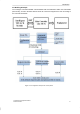
Introduction 1.5 Working Principle The Intelligent TFT-LCD Module communicates with the Customer’s MCU via Commands (HEX Code), and then the MCU would control its connected equipment to work according to the received commands. Figure 1.
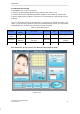
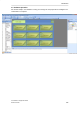
Introduction 1.6 Operation Processing Only 3 steps to use our TFT-LCD Module: 1. Design a group of Beautiful “Graphical User Interface”. (Ref. Picture 1.4-1) 2. Connect with customer’s MCU through RS232, RS485 or TTL level directly. Plug and play. 3. Write a simple program for MCU to control the TFT-LCD Module via Command. (HEX Code). That’s all. The TFT LCD module serial port command frame is composed of 5 data blocks, shown as the table 1-1.6.
Introduction 1.7 Software Operation We will offer simple "Tool Software" to help you to design the new project file for Intelligent TFTLCD Module on computer.
2Technical Parameters This chapter contains technical data on: - Physical Parameters: Physical Parameters Display - Hardware Parameters: Processor Memory Interface Power Supply - Storage & Test Electrical Characteristics Ambient Conditions Noise Immunity Radio Interference - Support Device Support Device STVI104WT-01 Equipment Manual Release 04/2016 -10-
Technical Parameters Physical Parameter Size 10.4 inch Resolution 800×RGB×600 Pixel Spacing 0.1905mm×0.0635mm (H×V) Color 65536 colors (16 bit) Viewing Area 211.2mm×158.4mm Display Dimension 212.6mm× 159.8mm Overall Dimension 247.8mm×193.7mm×15.8mm(N)/ 17.
Technical Parameters Interface Interface RS232/USB Interface Image downloading USB2.0 (12Mbps) & U storage Disk downloading Power Supply Rated voltage +12 V DC Permissible voltage range +6.0...+40.0 V DC Max. permissible transients +40V Time between two transients 50 sec minimum Internal Fuse Electronic Power consumption 3.
Technical Parameters Ambient Conditions Max. permissible ambient temperature Operation Storage -20℃~ +70℃ Relative humidity Operation Storage 55℃,85% Shock loading Operation Storage Vibration Operation Storage Barometric pressure Operation Storage -30℃~ +80℃ 60℃,90% 15 g/11 msec 25 g/6 msec 0.035 mm (10 - 58 Hz)/ 1 g (58 - 500 Hz) 3.5 mm (5 - 8,5 Hz)/ 1 g (8.
Technical Parameters Support Device Buzzer Support RTC Support USB port Support Touch Screen 4 Wire Resistance Default Font 6×12/ 8×16/ 12×24/16×32 /24×48 /32×64 /48×96 /64×128 (Dot Matrix) Picture Support JPG Format Storage Data Support Command Set Unified Simplified Command Sets STVI104WT-01 Equipment Manual Release 04/2016 -14-
3Interface Description This chapter contains the description of the interfaces: - VVC - NC - DOUT - DIN - GND - Baud Rate Please notify the interface type before ordering. RS232/ RS485/ TTL level interface.
Interface Description Communication Interface Definition: Pin Name Pin NO. Pin Type Interpret GND 1,2 P Power Ground DIN 4 I Data Input DOUT 5 O Data Output NC 3,6 VCC 7,8 None P Power Supply Input I: Input O: Output P: Power Note A: 1. Adopting the 8 Pin 2mm spacing socket. 2. Direction of the signal was defined with TFT-LCD Module; “I” refers to the signal from the user’s system transmitted to the TFT-LCD Module. 3.
4Accessories This chapter contains the accessories: - Double 8-pin Connect Cable - DB9 Connecting Cable - 8-pin Socket - Mini USB Cable - Converter - Bezel STVI104WT-01 Equipment Manual Release 04/2016 -17-
Accessories Accessory Name Model Double 8-pinCable L8 DB9 Cable LD 8-pin Socket S8 Mini USB Cable LU Converter UR2.0 UR4.0 UR1.0 Plastic Bezel Metal Bezel U Storage Disk PB-V043 PB-V050 PB-V056 PB-V070 PB-V080 PB-V104 MB-V035 MB-V043 MB-V050 MB-V056 MB-V070 MB-V080 MB-V101 MB-V104 Note Picture Optional: 10cm/20cm/30cm/65cm Connector: Standard DB9 Joint SMD-8 2.0mm with Lock USB to RS232 USB to RS485 USB to TTL For: 4.3”, 5”, 5.6”, 7”, 8”, 10.4” TFT-LCD Module. For: 3.5”,4.3”, 5”, 5.
5Installation This chapter contains the installation of plastic bezel.
6Physical Dimensions This chapter contains the information of Physical Dimensions.
7Command Set Table This chapter describes the Commands: - Access register interface - Access variant register interface - Write curve buffer interface STVI104WT-01 Equipment Manual Release 04/2016 -21-
Command Set Table Command List Function Comman d 0x80 Access register interface Data Distributed: register address (0x000xFF)+ write data Description Write register data at the specified address Distributed: register address (0x000xFF) + length of reading byte (0x000xFF) Start to read the register data of the specified byte length from specified address Response: register address (0x000xFF) + length of byte data + reading register data Read TFT LCD module response of the register 0x81 The TFT LCD
8 Electrical Components This chapter contains the brands of the components: - TFT Panel - Touch Screen - CPU - LCD Controller - Flash memory - Connecter - Capacitance - IC STVI104WT-01 Equipment Manual Release 04/2016 -23-
Electrical Components Components Supplier TFT Panel CPU LCD Controller Touch Screen Flash Memory Connecter Capacitance IC STVI104WT-01 Equipment Manual Release 04/2016 -24-
9Naming Rule This chapter contains the naming rule: As sample STVI070WT-01 Code Explain STV Company Code I 070 I=Industrial Type ; A=Advanced Type; C=Civil Type TFT Panel Dimension: 7 inch W W=Wide Voltage T T=With Resistive Touch Screen N=Without Touch Screen C=With Capacitive Touch Screen 0 0=RS232 1 Hardware Code STVI104WT-01 Equipment Manual Release 04/2016 4=RS485 1=TTL -25-
10International Certification This chapter contains the certification we passed: - CE Certificate - ROHS Certificate - FCC Certificate - ISO9001:2008 Quality System STVI104WT-01 Equipment Manual Release 04/2016 -26-
International Certification CE Certificate ROHS Certificate STVI104WT-01 Equipment Manual Release 04/2016 FCC Certificate ISO9001:2008 -27-
APPENDIX A MCU Sample Program B MCU Circuit Design C ESD Guidelines STVI104WT-01 Equipment Manual Release 04/2016 -28-
APPENDIX A. MCU Sample Program C8051 MCU C Language //----------------------------------------------------------------------------// Includes //----------------------------------------------------------------------------#include
void delay_ms(uchar n) { uint i,j; for(i=1000;i>0;i--) { for(j=25*n;j>0;j--) {;} } } //----------------------------------------------------------------------------// SysInit // “Initialization of system” //----------------------------------------------------------------------------void SysInit(void) { PCON |=0x80; SCON=0x50; TMOD=0x21; TH1=255; TL1=255; TR1=1; ES=0; TH0=0xDC; TL0=0x00; TR0=1; ET0=1; } //----------------------------------------------------------------------------// pic_str // “Picture switch
APPENDIX B.
APPENDIX C. ESD Guidelines What does ESD mean? Virtually all present-day modules incorporate highly integrated MOS devices or components.
APPENDIX Handling ESD assemblies A general rule is that assemblies should be touched only when this cannot be avoided owing to the work that has to be performed on them. Under no circumstances should you handle printedcircuit boards by touching device pins or circuitry. You should touch devices only if ● you are grounded by permanently wearing an ESD wrist strap or ● you are wearing ESD shoes or ESD shoe-grounding protection straps in conjunction with an ESD floor.
Glossary Baud rate Rate of speed at which data is downloaded. Baud rate is specified in Bit/s. Boot A loading process which downloads the operating system in the working memory of the operating unit. Command Set Hex Code, the MCU can control the TFT Module via the command set. Configuration file It can be created by the softwares. Download Download the image, configuration files and data through mini USB port or USB port. Download mode Through mini USB port or USB port.
Glossary Flash memory Programmable memory which can be electrically deleted and written to again segmentby-segment. Half Brightness Life The period of time after which the brightness tube only achieves 50% of the original value. Input field Enables the user to enter values which are subsequently sent to the MCU. MCU Micro Control Unit, it is widely used in the industrial control. Normal operation Operating unit operating mode in which messages are displayed and screens can be operated.
Glossary Output field Displays current values from the MCU on the operating unit. Process screen The display of process values and process progress on the operating unit in the form of screens, which may contain graphics, texts and values. RS485 Standard interface for serial data transfer at a very high transmission rate. Screen A screen displays all the logically related process data on the operating unit, whereby the individual values can be modified.