
User Manual
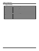
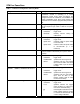
Table Of Contents

STN11xx PowerSave
Table 1 – PowerSave Configuration Summary Detail
Configuration Summary Line Sec. Description
CTRL MODE: <NATIVE/ELM327>
1.1 PowerSave control mode. Reports whether
PowerSave module is operating in a native
PowerSave control mode, where all settings are
configured via the ST commands, or an ELM327 Low
Power compatibility mode, where some settings are
overridden via the ELM327 programmable parameter
0E.
PWR_CTRL: LOW PWR = <LOW/HIGH>
1.5 PWR_CTRL output pin polarity. Specifies whether
the pin outputs a logic LOW or HIGH in low power
mode.
UART SLEEP: <ON/OFF>, <timeout> s
1.2.2 UART inactivity sleep trigger:
<ON/OFF> trigger on/off
<timeout> inactivity timeout setting in
milliseconds
UART WAKE: <ON/OFF>, <pulse min>-<pulse max> us
1.3.1 UART Rx pulse wakeup trigger:
<ON/OFF> trigger on/off
<pulse min> minimum UART Rx pulse width
in microseconds
<pulse max> maximum UART Rx pulse width
in microseconds (0 = no
maximum)
EXT INPUT: <LOW/HIGH> = SLEEP
1.2.3 SLEEP input polarity. Specifies whether it takes a
LOW or a HIGH on the SLEEP pin to put the device
to sleep.
EXT SLEEP: <ON/OFF>, <LOW/HIGH> FOR <time> ms
1.2.3 External SLEEP input sleep trigger:
<ON/OFF> trigger on/off
<LOW/HIGH> specifies the active logic level
<time> specifies how long the SLEEP
input must be held in the active
(“sleep”) state to put the device
to sleep.
EXT WAKE: <ON/OFF>, <LOW/HIGH> FOR <time> ms
1.3.2 External SLEEP input wakeup trigger:
<ON/OFF> trigger on/off
<LOW/HIGH> specifies the active logic level
<time> specifies how long the SLEEP
input must be held in the
inactive (“wake”) state to wake
the device from sleep.
VL SLEEP: <ON/OFF>, <</>>[!]<level> FOR <time> s
1.2.4 Voltage level sleep trigger:
<ON/OFF> trigger on/off
<</>> specifies whether the trigger
region is below (<) or above (>)
the <level> threshold setting
[!] this designator indicates that the
trigger voltage setting is invalid,
i.e. cannot be achieved with the
current voltage calibration
© 2009 ScanTool.net, LLC www.ScanTool.net STN11XXDSB