
Data Sheet
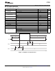
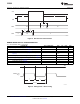
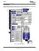
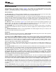
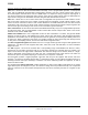
Table Of Contents
- FEATURES
- SOFTWARE FEATURES
- APPLICATIONS
- CC2541 WITH TPS62730
- DESCRIPTION
- ABSOLUTE MAXIMUM RATINGS
- RECOMMENDED OPERATING CONDITIONS
- ELECTRICAL CHARACTERISTICS
- GENERAL CHARACTERISTICS
- RF RECEIVE SECTION
- RF TRANSMIT SECTION
- CURRENT CONSUMPTION WITH TPS62730
- 32-MHz CRYSTAL OSCILLATOR
- 32.768-kHz CRYSTAL OSCILLATOR
- 32-kHz RC OSCILLATOR
- 16-MHz RC OSCILLATOR
- RSSI CHARACTERISTICS
- FREQUENCY SYNTHESIZER CHARACTERISTICS
- ANALOG TEMPERATURE SENSOR
- COMPARATOR CHARACTERISTICS
- ADC CHARACTERISTICS
- CONTROL INPUT AC CHARACTERISTICS
- SPI AC CHARACTERISTICS
- DEBUG INTERFACE AC CHARACTERISTICS
- TIMER INPUTS AC CHARACTERISTICS
- DC CHARACTERISTICS
- DEVICE INFORMATION
- TYPICAL CHARACTERISTICS
- APPLICATION INFORMATION
- References
- Additional Information
- Revision History

Time
DEBUG_CLK
P2_2
DEBUG_DATA
(to CC2541)
P2_1
DEBUG_DATA
(from CC2541)
P2_1
t
6
t
8
t
7
RESET_N
Time
DEBUG_CLK
P2_2
t
3
t
4
t
5
T0437-01
CC2541
www.ti.com
SWRS110D –JANUARY 2012–REVISED JUNE 2013
Figure 6. Debug Enable Timing
Figure 7. Data Setup and Hold Timing
TIMER INPUTS AC CHARACTERISTICS
T
A
= –40°C to 85°C, VDD = 2 V to 3.6 V
PARAMETER TEST CONDITIONS MIN TYP MAX UNIT
Synchronizers determine the shortest input pulse that can be
Input capture pulse duration recognized. The synchronizers operate at the current system 1.5 t
SYSCLK
clock rate (16 MHz or 32 MHz).
Copyright © 2012–2013, Texas Instruments Incorporated Submit Documentation Feedback 15
Product Folder Links: CC2541