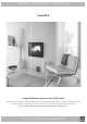
A S S E M B LY- A N D I N S T R U C T I O N S M A N U A L Scan DSA 11 Congratulations on your new Scan insert You have purchased a product by one of Europe’s leading manufacturer’s of wood-burning stoves, and we are sure that you will have years of pleasure with your purchase. To make the best possible use of your stove, it is important that you follow our advice and instructions. Please read this Assembly- and instructions manual before you start to assemble your stove.
CONTENTS 2 Table of contents Technical data……………………………………………..............……………………….. 3 Installation Certificate of testing Technical dimensions and data Dimensioned drawing for Scan DSA 11 Product registration number Additional accessories Type plate Loose parts Service kit Fitting……………………………………………………….................……………………....
T E C H N I C A L DATA 3 Installation Technical data and dimensions The house owner is responsible for ensuring that all necessary national and local safety measures are observed during installation and fitting and also responsible for observing the fitting and operating instructions detailed in this manual. Test in compliance with EN 13229 When you install any kind of fireplace or stove, you must inform the local authorities.
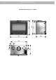
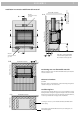
T E C H N I C A L DATA 4 590 468 794 730 420 166 113 143 640 656 Dimensioned drawing for Scan DSA 11
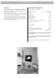
T E C H N I C A L DATA 5 Product registration number Type plate Take the insert out of the cassette and read the product registration number and make a note of it below. This number must be kept safe in case you need to contact us. All Scan wood-burning stoves are fitted with a type plate, that specifies the approval standards and the distance to flammable materials. Scan DSA 11 Insert fired by solid fuel Standard: A EN 13229 EC no.
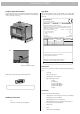
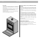
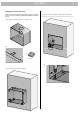
A S S E M B LY 6 Removing the packaging Scan DSA 11 is delivered secured to a pallet. To remove the packaging, please see below: Pull the insert out of the cassette. To remove the door: Loosen the Pointed screw, remove the rivet and lift the door off. Remove the two screws securing the cassette to the pallet.
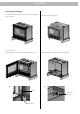
A S S E M B LY 7 Flammable materials Area for convection air out: 500 cm2 300 100 A-A B C C 340 B Flammable materials 300 A Minimum 300 mm distance to flammable materials Installation in connection with flammable material Area for convection air in: 350 cm2 100 Flammable materials Flammable materials B-B 50 A If the floor contains flammable materials the height above the floor must be at least 340 mm.
A S S E M B LY Floor plate The national and local building regulations must be followed regarding the size of a non-flammable base which is to cover the floor in front of the insert. Your local Scan dealer can give guidance on the rules concerning the protection of flammable material around the stove. The floor plate’s function is to protect flooring and flammable material against any embers.
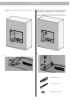
A S S E M B LY 9 Fitting the cassette and insert NB: If you have chosen to fit the insert with convection connection pieces, go to page 14, and then continue the installation as described below. To secure the cassette, pre-drill the 4 holes with a 10 mm drill bit. Fit the clips. They will be used later for securing the trim. D D E 6 x clips E Place the cassette in the hole/surrounding.
A S S E M B LY 10 Set the adjustment screws with an open-end spanner so the cassette is level. Fit the rawl plugs, screws and washers. Ensure that the cassette is level before tightening. For tightening you can also use the supplied Torx key from the loose parts bag in the insert’s combustion chamber. G F G F 4 x Rawl plugs 10 x 50 4 x Torx screws 6 x 50 4 x Washers Ø 8 / Ø 16 x 1.
A S S E M B LY 11 NB: If you have chosen to install your Scan DSA 11 with a fan, go to page 14 for installation of the fan. Then continue with the installation below. Fit the insert into the cassette. The stove’s pivot pins must fit snugly in the holes in the cassette so that the stove is secured tightly. Pivot pins on insert Mount the trim.
A S S E M B LY 12 Fitting the flue connection piece The flue connection piece and the gasket for this is provided loose in the insert’s combustion chamber. Before fitting the flue connection piece, the smoke deflector plate must be removed. This must be done as follows: Fit the gasket provided to the flue connection piece. Lift the smoke deflector plate and remove the pins. Gasket H H Fit the flue connection piece in the flue outlet with 5 x Allen screws.
A S S E M B LY Fit the smoke deflector plate and the door of the insert.
FITTI NG OF ACC ESSOR I ES 14 Fitting the convection connection pieces See page 9 for how to fit and tighten the cassette. Cut through the fastening points in the cover plates for the convection connection pieces with pliers and remove the plates. When the cassette has been tightened, fit the convection connection pieces. Fit these and tighten them through the hole for the flue connection piece.
FITTI NG OF ACC ESSOR I ES 15 Fitting the fan The Installation must be planned and executed in accordance with national and local regulations. In order to ensure correct installation, an authorised electrician must carry out the installation of the fan. Fan Scan A/S disclaims all liability for the installation of the fan. Cable relief and screws for bracket Regulator ES 904 Cable for connection between ES 904 and fan Removing the damper Removing the grid Remove screws and damper.
FITTI NG OF ACC ESSOR I ES Cable with male connector for fan. Fit the cable with female connector for ES 904 into the bracket and attach the cable to the cable relief and place it inside the hole in the cassette. Remove the bracket from the male connector. Position the insert in the cassette. Fit the bracket onto the cassette with the two supplied screws. Insert the male connector from the fan in the female connector for ES 904.
FITTI NG OF ACC ESSOR I ES 17 2 1 4 5 6 7 3 N 8 3 BL N 3 2 WH 2 L N BR WH BL BR 1 PE N 1 Connection table for fan BR WH BL ES 904 Fan Motor Conductor Cable colour L Line (phase) Brown N Neutral Blue PE Protection earth Yellow/Green Colour codes for cables Cable colour BR Brown WH White Yellow/Green N Blue BL Black
I NSTRUCTION FOR USE CB Technology (Clean Burning) Primary air The stove is equipped with the clean burning technique. In order to ensure an optimal combustion of released gases under the incineration process, air will pass through a specially developed canal system. The heated air is led into the combustion chamber through the small holes at the rear of the burn chamber. This air volume is controlled by the combustion rate and thus cannot be regulated.
I N S T R U C T I O N S F O R H E AT I N G Environmentally-Friendly Heating Avoid restricting your wood-burning stove to an extent where no flames are visible during the degasifying period, as this leads to particularly inefficient heating. The gases released by the wood do not burn due to the low temperature in the combustion chamber. Part of the gas condenses in the wood-burning stove and flue system as soot, and this could lead to your chimney catching fire.
I N S T R U C T I O N S F O R H E AT I N G General Notes Your wood stove is not designed for continual heating for periods of over 24 hours. Please note! Parts of the wood-burning stove, especially the outer surfaces, become hot during use. Please exercise due care. Handling fuels Selecting Wood/Fuel Never empty ashes into a flammable container. Ashes can contain glowing embers long after you finish using your wood stove.
MAINTENANCE Maintaining your wood-burning stove Apart from regular chimney sweeping, your wood-burning stove does not require any regular maintenance. Use only original replacement parts for maintenance and repairs of your stove. Note! Make sure the stove is cold before starting maintenance or repair work. Coated surfaces Clean your wood-burning stove by dusting with a dry, lint-free cloth. If the topcoat is damaged, you can purchase a repair spray from your authorised Scan dealer.
T R O U B L E S H O OT I N G Smoke escaping • Damp wood • Chimney not drawing properly • Chimney is not properly dimensioned for the stove • Check if the smoke gas pipe/chimney are blocked • Is the chimney the right height for its surroundings? • Vacuum in room • The door is opened before the embers have burned down sufficiently Wood burning too quickly • The air valves are set incorrectly • The smoke deflector plates is incorrectly mounted or missing • Inferior firewood (waste wood, pallets etc.
Version GB 90084500-5 08.02.