
Specifications

CV-A10 CL and CV-A70 CL
6. Functions and Operations
6.1. Basic functions
The A10CL-A70CL camera is a progressive scan camera with 10 or 8 bit video output in single
channel Camera Link. An analogue iris video signal can be used for lens iris control. The camera
has 1/2, 1/4 or 1/8 partial scanning for faster frame rates. Vertical and horizontal binning is
possible. The H and V binning can operate separate or together. 2:1, 3:1 a 4:1 binning is
available. If same H and V binning ratio is selected, the image aspect ratio is correct. With 4:1 V
and H binning, the sensitivity is 16 times higher. Binning is only on CV-A10 CL.
There are 5 trigger modes. Normal continuous, edge pre-select, pulse width control, sensor gate
control and reset continuous trigger. The accumulation can be LVAL synchronous or LVAL a-
synchronous. For trigger modes using fast shutter times, smearless read out is possible.
In the following some of the functions are shown in details.
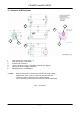
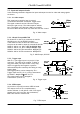
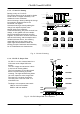
6.1.1. Restart continuous trigger mode
The RCT mode makes it possible to use a lens with video controlled iris in triggered applications.
The camera is running continuously,
and the iris is controlled from the iris
video output. When a trigger pulse is
applied, the scanning is reset and
restarted, the previous signal is
dumped with a fast dump readout, and
the new triggered exposure is started.
This fast dump readout has the same
effect as “smearless readout”. Smear
over highlighted areas are reduced for
the triggered frame.
Trigger
SG
Exposure
Video out
Dump
Read out
Continuous video out Continuous video outTriggered
Frame
Trigger
SG
Exposure
Video out
Dump
Read out
Continuous video out Continuous video outTriggered
Frame
Fig. 9. Restart continuous trigger mode
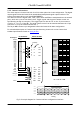
6.1.2. Sensor Gate Control
This function is for applications where a strobe flash is the only illumination, and where the
exact time for the strobe firing is not known. The time window for the strobe firing can be up to
several frames. The resulting video readout can also be delayed by this function. It makes the
synchronization of the frame grabber more flexible.
The Sensor Gate Control signal will inhibit the internal SG signal so the accumulation can
continue.The SG signal is an internal signal, which is low when the accumulated charge on the
photo diode array is transferred to the
vertical ccd registers for readout. When
the Sensor Gate Control input is high, the
internal SG pulse is inhibited, and the
signal accumulation on the photo diode
array can take place. When the strobe
flash is fired, the Sensor Gate Control
signal can be low. The resulting video is
then read out after the first FVAL (or SG),
following the falling edge of Sensor Gate
Control signal.
Sensor Gate
Control
SG
FVAL
Video out
SG inhibit
Strobe Flash
Strobe can be fired here
Sensor Gate
Control
SG
FVAL
Video out
SG inhibit
Strobe Flash
Strobe can be fired here
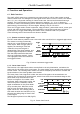
The SG signal is placed in line #28.(fig.32.)
Fig. 10. Sensor Gate Control
- 7 -