
User manual


1.1 Application Interface 9
1.1.2 3D view panel
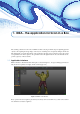
The 3D view panel shown in Figure 1.3 allows to see in three dimensions the objects currently selected in
the project management panel. Each of the selected elements is positioned within a global reference system,
which orientation is shown with the axes in the lower left corner of the window.
Figure 1.3: 3D view panel.
To change the view point of the currently shown scene (rotating around the object, scaling, traslation and so
on) a few mouse-keybord combination can be used:
• free rotation;
• + or + : free translation;
• + : rotation bound on Y axis;
• + : rotation bound on X axis;
• + : rotation bound on Z axis;
• Rotation : scales the portion of data currently framed;
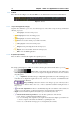
• : access the menu contextual to the selected data type;
• + : changes the position of the light source in the scene;
•
: with an active selection tool, allows to select part of the data, it could be used also for some
features of the toolbar;
•
+ : with an active selection tool it allows to deselect part of the data that was previously
selected.
A few of these actions can also be activated by features of the toolbar (Sect. 1.1.3). The application establishes
the barycenter of the selected elements as default rotation center. However, if the button Rotation centered
on view position, the rotation center is positioned at the barycenter of the portion of data currently visualized.
In the upper left corner it is shown a frame providing information related to the current visualization, such as
the number of visualized elements, the number of points that constitutes them, and the dimension of their
bounding box. In case the content of such frame was difficult to be read, due to its overlap with the visualized
data, double clicking on it with the mouse allows to invert its color, improving the visualization.