
User manual


34 Chapter 2. Using IDEA
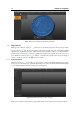
This allows to easily identify situations in which a scan was not appropriately aligned: if so, the distance
value associated to that scan will be significantly higher that the others.
Given the complex issue, the global alignment procedure is one of the most complicated in terms of time
consumption, especially for objects made by many different scans.
If the alignment was to be interrupted by the user (with the Stop button placed in the lower bar that
appears launching the tool) the improvements made until that moment are automatically applied to the
processed scan set.
2.3 Preparing to generate the model
Before generating the 3D model it is necessary to check that this conditions are respected:
• all scans must be appropriately aligned;
•
all scans must be clean: remove the outliers and the framed parts of data that one does not want to
include in the final model; the outliers are parts of the range images that don’t’ belong to the surface
of the object (they may be caused by poor light conditions, or if the material of the object does not
cooperate with the light). To remove the undesired elements, IDEA provides a number of manual
tools, described in Sect. 1.1.3.4, or automatic ones (ref. Sect. 1.1.3.7).
• optimized alignment through the global alignment (ref. Sect. 2.2.3.2).
2.4 Model Generation
IDEA adds to the procedures for managing the range images the features to generate and manage the triangle
mesh. The meshes can be generated from the scans, imported by files and exported in some standard
exchange formats.
2.4.1 Mesh generation
The mesh generation can be carried out starting from the data of one or more range images. Once selected
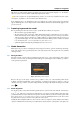
the data to convert in mesh, by clicking the button will appear a panel (Figure 2.26) in which it is possible to
set the generation parameters.
Figure 2.26: Mesh generation panel.
Based on the type of the object of interest, it is possible to chose one of the standard profiles shown
in Figure 2.26, that automatically set the parameters of generation appropriate to that type of object,
otherwise it is also possible to customize such parameters acceding to the advanced settings section with
button .
2.4.2 Datum alignment
Zeroing the position of the 3D model in the global reference system can be done with the “Datum Align-
ment tool. This tool is often used to make the base of an object coincide with the plane XY of the
system. In the flat area of the mesh that corresponds to the base if the object, the user creates a plane with
the tool Approximate selection with a plane (ref. Sect. 1.1.3.8); the datum alignment moves the object so that
the plane created on it base coincides on the plane XY of the system.
Usually this kind of alignment allows to move a mesh so that 3 of its planes coincide with the same number
of planes calculated and saved in the project (that always has at least the system planes). The planes are