
User manual


2. Using IDEA
This chapter describes how to use IDEA the software to create a digital model of a physical object. With
version 1.1 of IDEA is now possible to use the Turn Table which allows for a very high degree of automation
during the acquisition and generation of the digital model. The process to configure the scanner and digitize
an object is subdivided in four main steps:
1. optical set-up and calibration (Sect. 2.1)
: relates to the physical configuration of the scanner to
operate with a specific working area. It is subdivided in two steps:
(a) Optical set-up (Sect. 2.1.1)
: once the scanning area is chosen, the position and the orientation
of the cameras, together with their focus, are to be configured;
(b) Calibration of the optical head (Sect. 2.1.2)
: allows obtaining the scanner’s operational param-
eters for the chosen scanning area;
2. Acquisition and alignment (Sect. 2.2)
: explains the acquisition methods and how to activate the
alignment tool; if available the turn table, it introduces its calibration that allows the automatic
alignment of object to be scanned placed on the turn table;
3. Preparation to the model generation (Sect. 2.3)
: describes what actions need to be performed prior
to the 3D model generation; such as the optimization of each individual scan’s alignment, the use of
the cleaning tools for the range images,and the optimization of the alignment between scans;
4. Generating a model (Sect. 2.4)
: describes the operations linked to the generation of the triangle
meshes.
2.1 Optical set-up
Scan in a box can be set to operate on the scanning areas the user chooses. Setting the scanner to operate on
a specific work area is easy because it just depends on the distance between the scanner and the object. The
Table 2.1 displays a list of scanning areas and their relative work distance to which the scanner has to be
placed in order to work.
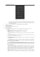
Together with the scanner is provided a calibration master that has to be used for the optical setup and the
consequent calibration. Once chosen the working area one has to place the master as apart from the scanner
as referred to in Table 2.1 and orient it so that it will be framed frontally (ref. Figure 1.4). The calibration
master has 3 different patterns which are to use based on the cho- sen scanning area (ref. Figure 2.2 and
Table 2.2). At this stage, the scanner can be configured to operate in the chosen scanning area.