Software Manual IDEA – The Software Version 1.
WWW. SCANINABOX .
Contents I Part One 1 IDEA - the application for Scan in a Box . . . . . . . . . . . . . . . . . . . . . . . . . 7 1.1 Application Interface 1.1.1 1.1.2 1.1.3 Project management panel . . . . . . . . . . . . . . . . . . . . . . . . . . . . . . . . . . . . . . . . . . 8 3D view panel . . . . . . . . . . . . . . . . . . . . . . . . . . . . . . . . . . . . . . . . . . . . . . . . . . . . 9 Toolbar . . . . . . . . . . . . . . . . . . . . . . . . . . . . . . . . . . . . . . . . . . . . . . . . . . . . .
2.4.2 II 3 Datum alignment . . . . . . . . . . . . . . . . . . . . . . . . . . . . . . . . . . . . . . . . . . . . . . . . . . 34 Part Two Glossary . . . . . . . . . . . . . . . . . . . . . . . . . . . . . . . . . . . . . . . . . . . . . . . . . . . . .
I Part One 1 IDEA - the application for Scan in a Box 7 1.1 Application Interface 2 Using IDEA . . . . . . . . . . . . . . . . . . . . . . . . . . . 17 2.1 2.2 2.3 2.
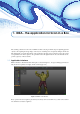
1. IDEA - the application for Scan in a Box The scanning software for Scan in a box is IDEA: it allows carrying out all the steps for digitizing physical objects, form capturing the range images of the object to obtaining and consequently editing its 3D model. This manual aims to describe the interface of the application, the main steps for using the scanner, the optical set-up/calibration, from the capture to the generation of the 3D digital model.
Chapter 1. IDEA - the application for Scan in a Box 8 The project management panel shows and manages all the data collected in the project through the various steps of the digitizing process (Sect. 1.1.1). The 3D view panel shows the data of the project; most of the possible interactions with the data is performed in this panel (Sect. 1.1.2). Finally, the toolbar contains all the features provided by the application for the editing of the data (Sect. 1.1.3). 1.1.
1.1 Application Interface 1.1.2 9 3D view panel The 3D view panel shown in Figure 1.3 allows to see in three dimensions the objects currently selected in the project management panel. Each of the selected elements is positioned within a global reference system, which orientation is shown with the axes in the lower left corner of the window. Figure 1.3: 3D view panel.
Chapter 1. IDEA - the application for Scan in a Box 10 1.1.3 Toolbar The toolbar shown in Figure 1.4 collects all IDEA’s tools, subdivided in colors based on their function. Figure 1.4: Toolbar. 1.1.3.1 Project management (orange) Organizes the commands to open, close, save and load projects; it also allows to import and export individual elements of a project. 1.1.3.
1.1 Application Interface 11 Figure 1.6: Cameras’ control panel. – Exp: regulates the exposure time, that is the interval (in milliseconds) during which the camera sensor integrates the light: the greater the exposure time, the brighter the image but the slower the camera acquisition rate. The button Reset to defaults allows to reset such parameters to their original values. 1.1.3.3 Alignment (light blue) Collects all the tools to align data (Sect. 2.2.3). 1.1.3.
Chapter 1. IDEA - the application for Scan in a Box 12 aligned or that create areas of noise. All of the described tools allow, pressing the right button of the mouse, to shift the current selection area; moreover, pressing the Esc key, it is possible to cancel the currently shown selection. 1.1.3.5 Rendering (pink) These are the commands that modify the data rendering settings in the 3Dview window. • 1.1.3.
1.
Chapter 1. IDEA - the application for Scan in a Box 14 – “Conservative: it’s the most sophisticated smoothing tool to preserve the surface details. Figure 1.10: Noise reduction panel. • Decimate: reduces the number of triangles that constitute the mesh, optimizing the surface areas with less details.
1.1 Application Interface 15 selected elements in the 3D view panel. One selected the hole to fill, it’s possible to proceed clicking on the Fill button. The combo-box Curvature filling allows choosing between a filling method that follows the curvature of the object or a planar filling. The triangles added in this operation will be marked as selected, therefore will be red. It’s possible to cancel the last operation (Ctrl+Z to cancel,Ctrl+Y to re-apply) were the resulting filling to be unsatisfactory..
2. Using IDEA This chapter describes how to use IDEA the software to create a digital model of a physical object. With version 1.1 of IDEA is now possible to use the Turn Table which allows for a very high degree of automation during the acquisition and generation of the digital model. The process to configure the scanner and digitize an object is subdivided in four main steps: 1. optical set-up and calibration (Sect. 2.
Chapter 2. Using IDEA 18 Scanning Area (mm) Distance (mm) 100 × 80 150 × 120 200 × 160 250 × 200 300 × 240 350 × 280 400 × 320 450 × 360 500 × 400 200 320 448 560 672 784 896 1008 1120 Table 2.1: relationship between scanning area and distance. Figure 2.1: Frontal frame of the calibration master. (a) Anterior panel pattern 400×300 pitch 15.00 mm. (b) Posterior panel pattern 200×150 pitch 7.50 mm e pattern 100×100 pitch 5.00 mm. Figure 2.2: Calibration masters’ pattern.
2.1 Optical set-up 19 Area Pattern From 80 to 120 mm From 120 to 200 mm From 200 to 350 mm From 400 to 500 mm 100×100 pitch 5.00 mm 200×150 pitch 7.50 mm 400×300 pitch 15.00 mm 400×400 pitch 30.00 mm Table 2.2: Relationship scanning area – calibration master’ pattern. 2.1.1 Optical set-up mode The first time the scanner is used, and every time the scanning area changes, the scanner has to be configured and then calibrated.
Chapter 2.
2.1 Optical set-up 21 Figure 2.6: Frame of the calibration master. Figure 2.7: Triangulation principle.
Chapter 2. Using IDEA 22 • open the iris of the camera’s lenses as wide as possible; higher the exposure time if the images of the framed master are too dark; regulate the focus of the cameras so that the circles of the master are as sharp as possible; tighten the focus screws (ref. Figure 2.8); Figure 2.8: Focus setup screw. • set the exposure time based on Table 2.
2.1 Optical set-up 23 • the approximate framed area; • the type of master he/she wants to use. Figure 2.10: Optical head calibration settings. Once confirmed these choices IDEA starts the Calibration mode as shown in Figure 2.11.The purpose of the calibration is to acquire a sequence of images to elaborate in order to produce entry data for the procedure that calculates the scanner’s operational parameters. Figure 2.11: Calibration mode. The calibration panel (Figure 2.
Chapter 2. Using IDEA 24 Figure 2.12: Calibration panel. • Erase current pair: erases the current image pair; • Calibrate: starts the calibration procedure once finished the image acquisition cycle; the procedure elaborates on the acquired data and determines the operational parameters of the scanner.
2.2 Capture and alignment 25 the frame in the center of the master and acquire the ninth pair of images; to confirm and get to the following position click on Next pair The recalibration procedure only requires the acquisition of 3 pairs of images namely the first, the second and the third; it has to be used when the optical setup of the scanner is not modified and the user wants to perfect the operational parameters of the scanner if it has been a while since it was calibrated.
Chapter 2. Using IDEA 26 2.2.1 Free mode acquisition When the acquisition procedure is initiated, with the Open head button shown in Figure 2.14. , it will be displayed the interface Figure 2.14: Acquisition interface. The scan panel (Figure 2.15) shows a combo-box by which the following options can be chosen: • 3D Scan: allows to perform 3D scans in free mode, described in this section; • Setup ottico: allows to go back to the physical configuration of the scanner (ref. 2.1.1).
2.2 Capture and alignment 27 Before launching the 3D scan it is necessary to go through a sequence of operations (ref. Figure 2.17): (a) (b) (c) Figure 2.17: Preparation to acquisition. • Live activation: clicking on the button Turn on live two windows will appear in the 3D view panel.
Chapter 2. Using IDEA 28 distance is appropriate; • Projector’s focus regulation (optional)): if the black vertical line appears not to be sharp enough (as shown in Figure 2.17.b) set the projector’s focus to obtain a satisfying definition (ref. Figure 2.17.c). It is now possible to scan the surface of interest through the button 3D Scan acquired data is displayed in the 3d view window as in Figure 2.18. . At the end of the scan the Figure 2.18: Result of an acquisition procedure. 2.2.
2.2 Capture and alignment 29 • Optical Setup: allows to return to the physical configuration of the scanner (ref. 2.1.1). • Batch Turn Table 3D Scan: allows to perform multiple acquisitions through a single scan command; the object will be automatically oriented by the turn table; • Turn Table Calibration: allows to calibrate the turn table rotation axis, enabling the option to automatically align the scans. (a) (b) (c) Figure 2.
Chapter 2. Using IDEA 30 Figure 2.21: Result of multiple 3D Scan with the Turn Table. 2.2.3 Alignment tool IDEA provides a Manual alignment tool that uses some directions given by the user. The procedure Globale alignment can be used once all the scans have been aligned to each other with the manual alignment tool, and the undesired parts of data have been removed. This tool allows to overall optimize the undesired parts of data.
2.2 Capture and alignment 31 select the scans that will remain fixed during alignment, whereas the bottom one allows to select the ones that will change, that is, the ones that will be moved during alignment. To align select at least one fixed scan (in the top list) and one moving (in the bottom list). When an element is selected in one list it will become impossible to select it in the other, and its name will be marked in red (ref. Figure 2.23.a).
Chapter 2. Using IDEA 32 (a) (b) Figure 2.24: three-point based alignment of fixed and moving scans.
2.2 Capture and alignment 33 Align the position of the two scans will be optimized, and the descriptive values of average and standard deviation regarding the distance between the two surface are displayed (ref. Figure 2.24.b). Moreover, to ease the process of selecting the common points is possible to select the box use texture color to visualize the texture associated to the object one has to align.
Chapter 2. Using IDEA 34 This allows to easily identify situations in which a scan was not appropriately aligned: if so, the distance value associated to that scan will be significantly higher that the others. Given the complex issue, the global alignment procedure is one of the most complicated in terms of time consumption, especially for objects made by many different scans.
2.4 Model Generation 35 Figure 2.27: Datum alignment panel. divided in 2 groups, one of the fixed planes, containing the system planes and one for the planes built on the mesh one has to align. The alignment is defined with the button create pair which associates a fixed plan with a moving one: a list containing one to three pairs of planes, each one with a reference plane (fixed) and a moving plane of the mesh, is created; such list orders with decreasing priorities the alignment bindings.
II Part Two 3 Glossary . . . . . . . . . . . . . . . . . . . . . . . . . . . .
3. Glossary USB bus the Universal Serial Bus is an interface that allows to easily connect different devices to a computer. Theoretically, the USB bus 2.0 could transfer up to 50 MB/s but practically a high-performance desktop computer can only reach approximately 40 MB/s; most of the notebook and embedded devices do not even reach 40 MB/s; Range image it is the three-dimensional equivalent of a photo: it stores the 3D coordinates, arranged within an acquisition grid, of the captured data.