OPERATOR’S MANUAL Tiger Cat Models: STC48V-19KAI STC48V-23CV STC48V-25CV STC48V-25CV-SS STC48V-26BS STC52V-25CV STC52V-27CV STC52V-27CV-SS STC61V-25CV STC61V-27CV STC61V-27CV-SS Congratulations on owning a Scag mower! This manual contains the operating instructions and safety information for your Scag mower. Reading this manual can provide you with assistance in maintenance and adjustment procedures to keep your mower performing to maximum efficiency.
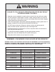
WARNING FAILURE TO FOLLOW SAFE OPERATING PRACTICES MAY RESULT IN SERIOUS INJURY OR DEATH. • Read this manual completely as well as other manuals that came with your mower. • DO NOT operate on steep slopes. To check a slope, attempt to back up it (with the cutter deck down). If the machine can back up the slope without the wheels slipping, reduce speed and use extreme caution. • Under no circumstances should the machine be operated on slopes greater than 15 degrees.
Table of Contents R Table of Contents SECTION 1 - GENERAL INFORMATION. ..................................................................................1 1.1 Introduction............................................................................................................................................1 1.2 Direction Reference............................................................................................................................1 1.
Table of Contents R SECTION 6 - ADJUSTMENTS..................................................................................................22 6.1 PARKING BRAKE ADJUSTMENT.............................................................................................................22 6.2 TRAVEL ADJUSTMENTS...........................................................................................................................22 6.3 Throttle Control and Choke Adjustments....................................
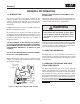
Section 1 R GENERAL INFORMATION 1.1 Introduction USE ONLY SCAG APPROVED ATTACHMENTS AND ACCESSORIES. Your mower was built to the highest standards in the industry. However, the prolonged life and maximum efficiency of your mower depends on you following the operating, maintenance and adjustment instructions in this manual. Attachments and accessories manufactured by companies other than Scag Power Equipment are not approved for use on this machine. See Section 8, Paragraph 8-1.
Section 1 R 1.4 Symbols SYMBOL DESCRIPTION SYMBOL DESCRIPTION Choke Transmission Parking Brake Spinning Blade 48071S On/Start Spring Tension on Idler Off/Stop Oil Falling Hazard Thrown Object Hazard Fast Slow Continuously Variable - Linear Cutting Element - Basic Symbol Pinch Point Cutting Element - Engage Hour meter/Elapsed Operating Hours Cutting Element - Disengage STT Models CE Mark 481039S Seat must be installed under the seat hold down bracket during installation.
Section 2 R SAFETY INFORMATION 2.1 Introduction Danger Your mower is only as safe as the operator. Carelessness or operator error may result in serious bodily injury or death. Hazard control and accident prevention are dependent upon the awareness, concern, prudence, and proper training of the personnel involved in the operation, transport, maintenance and storage of the equipment. Make sure every operator is properly trained and thoroughly familiar with all of the controls before operating the mower.
Section 2 R 7. If the operator(s) or mechanic(s) cannot read English or Spanish, it is the owner's responsibility to explain this material to them. 12. DO NOT add fuel to a running or hot engine. Allow the engine to cool for several minutes before adding fuel. Never fuel indoors or inside enclosed trailers. 8. DO NOT wear loose fitting clothing. Loose clothing, jewelry or long hair could get tangled in moving parts.
Section 2 R 3. To prevent tipping or loss of control, start and stop smoothly, avoid unnecessary turns and travel at reduced speed. 15. The machine and attachments should be stopped and inspected for damage after striking a foreign object, and damage should be repaired before restarting and operating the machine. 4. When using any attachment, never direct the discharge of material toward bystanders or allow anyone near the machine while in operation. Caution 5.
Section 2 R 2.5 Roll-over protection system Lower the roll bar only when absolutely necessary. 1. To lower the roll bar, loosen the tension knob on both the left hand and right hand bar. See Figure 2-1. WARNING 2. Remove the hairpin cotter pins and remove the two (2) lock pins. See Figure 2-2. Keep the roll bar in the raised and locked position and the seat belt securely fastened during operation. Failure to do so could cause serious injury or loss of life. 3. Lower the roll bar to the down position.
Section 2 R It is recommended that the seat belt be inspected on a daily basis for signs of damage. Any seat belt system that shows cuts, fraying, extreme or unusual wear, significant discoloration due to UV exposure, dirt or stiffness, abrasion to the seat belt webbing, or damage to the buckle, latch plate, hardware or any other obvious problem should be replaced immediately. WARNING Reduce speed when turning, operating on slopes, slick or wet surfaces. Allow extra distance to stop.
Section 2 R 2.6 Maintenance Considerations & storage WARNING 1. Never make adjustments to the machine with the engine running unless specifically instructed to do so. If the engine is running, keep hands, feet, and clothing away from moving parts. Hydraulic fluid is under high pressure. Keep body and hands away from pinholes or nozzles that eject hydraulic fluid under high pressure. If you need service on your hydraulic system, please see your authorized Scag dealer.
Section 2 R 2.8 SAFETY AND INSTRUCTIONAL DECALS WARNING INSTALL BELT COvER BEFORE OPERATING MACHINE READ OPERATOR'S MANUAL 483402 R FORWARD 483407 F REvERSE 481568 WARNING 483406 Operation of this equipment may create sparks that can start fires around dry vegetation. A spark arrestor may be required. The operator should contact local fire agencies for laws or regulations relating to fire prevention requirements. 483900 ! CAUTION Avoid injury from burns.
Section 3 R SPECIFICATIONS 3.1 ENGINE General Type.................................................................................................Heavy Duty Industrial/Commercial Gasoline Brand...........................................................................................................................Briggs & Statton, Kohler, Kawasaki Horsepower: (Scag Model STC48V-19KAI)...................................................................................... 19 HP (Spec.
Section 3 R Tire Pressure: Front Caster....................................................................................................................................................... 25 PSI Drive................................................................................................................................................................... 12 PSI Fuel Tanks............................................. Dual 4-Gallon Seamless Polyethylene Tanks with Large Opening and Fuel Cap Seat..
Section 4 R OPERATING INSTRUCTIONS 2. Mower Deck Switch (Figure 4-1). Used to engage and disengage the mower drive system. Pulling up on the switch will engage the deck drive. Pushing down on the switch will disengage the deck drive. CAUTION Do not attempt to operate this mower unless you have read this manual. Learn the location and purpose of all controls and instruments before you operate this mower. 3. Engine Choke Control (Figure 4-1). Used to start a cold engine. 4.
Section 4 R 6. Fuse Holders (Figure 4-1). Two 20-amp fuses protect the mower’s electrical system. To replace fuses, pull fuse out of the socket and install a new fuse. 14. Deck Release Lever (Figure 4-1). Used to lock the cutter deck in the transport position. Push the foot pedal forward and pull back on the release lever to release the cutter deck for normal mowing. 7. Left Steering Control (Figure 4-1). Used to control the mower's left wheel when traveling forward or reverse. 15.
Section 4 R 4.4 STARTING THE ENGINE Learn to feather the steering controls to obtain a smooth operating action. Practice operating the mower until you are comfortable with the controls before proceeding to mow. CAUTION DO NOT USE STARTING FLUIDS. Use of starting fluids in the air intake system may be potentially explosive or cause a “runaway” engine condition that could result in engine damage and/or personal injury.
Section 4 R 4.6 ENGAGING THE DECK DRIVE (CUTTER BLADES) Reverse Travel Caution 1. Set the throttle at about 3/4 speed. Do not attempt to engage the deck drive at high speed as this shortens the electric clutch life — use only moderate engine speed when engaging the deck drive. Disengage power to the mower before backing up. Do not mow in reverse unless absolutely necessary and then only after observation of the entire area behind the mower. 2.
Section 4 R 4.7 HILLSIDE OPERATION 4.9 AFTER OPERATION 1. Wash the entire mower after each use. Do not use high pressure spray or direct the spray onto electrical components. WARNING - IMPORTANT - DO NOT operate on steep slopes. To check a slope, attempt to back up it (with the cutter deck down). If the machine can back up the slope without the wheels slipping, reduce speed and use extreme caution. Under no circumstances should the machine be operated on slopes greater than 15 degrees.
Section 4 R 4.11 MOVING MOWER WITH ENGINE STOPPED 4. Keep mower and discharge chute clean. 5. When mowing wet or tall grass, mow the grass twice. Raise the mower to the highest setting for the first pass and then make a second pass to the desired height. To “free-wheel” or move the mower around without the engine running, rotate the dump valve levers counterclockwise. See Figure 4-4. Disengage the parking brake and move the mower by hand.
Section 4 R 3. Insert the lanyard pin into the cutting height index at the desired cutting height. Push forward on the deck lift foot lever, hold in place and pull back on the deck release lever. See Figure 4-6. Slowly release the foot pedal. A deck height decal is located on the cutting height index as an aid in adjusting the deck to the desired height. See Figure 4-5. STC 2006 DRL DECK RELEASE LEVER Figure 4-6. Deck Release Lever 4.14 Towing (optional hitch accessory) 1.
Section 5 R TROUBLESHOOTING CUTTING CONDITIONS Condition Cause Stringers - Occasional Low engine RPM Blades of Uncut Grass Width of Deck SGB020 Cure Run engine at full RPM Ground speed too fast Slow speed to adjust for conditions Wet grass Cut grass after it has dried out Dull blades, incorrect sharpening Sharpen blades Deck plugged, grass accumulation Clean underside of deck Belts slipping Adjust belt tension Streaking - Strips of Dull, worn blades Uncut Grass in Cutting Path Incorrect bla
Section 5 R TROUBLESHOOTING CUTTING CONDITIONS (CONT'D) Condition Cause U ne v en C ut on F lat Lift worn from blade Ground - Wavy High-Low Appearance, Scalloped Blade upside down Cut, or Rough Contour Cure Replace blade Mount with cutting edge toward ground Deck plugged, grass accumulation Clean underside of deck Too much blade angle (deck pitch) Adjust pitch and level Deck mounted improperly See your authorized SCAG dealer Bent spindle area See your authorized SCAG dealer Dull blade Sharpen
Section 5 R TROUBLESHOOTING CUTTING CONDITIONS (CONT'D) Condition Cause Scalping - Blades Hitting Low tire pressures Dirt or Cutting Very Close to the Ground Ground speed too fast Width of Deck Cure Check and adjust pressures Slow speed to adjust for conditions Cutting too low May need to reduce ground speed, raise cutting height, change direction of cut, and/or change pitch and level Rough terrain May need to reduce ground speed, raise cutting height, and/or change direction of cut Ground speed
Section 6 R ADJUSTMENTS 6.1 PARKING BRAKE ADJUSTMENT STC2002BA WARNING Do not operate the mower if the parking brake is not operable. Possible severe injury could result. LOOSEN HERE The parking brake linkage should be adjusted whenever the parking brake lever is placed in the “ENGAGE” position and the parking brake will allow the mower to move. If the following procedures do not allow you to engage the parking brake properly, contact your Scag dealer for further brake adjustments.
Section 6 R Neutral Adjustment Tracking Adjustment 1. Be sure the dump valve levers are in the run position and the steering control levers are in the neutral lock position. Caution 2. With an operator in the seat, start the engine and disengage the parking brake. Stop the engine and remove the key from the ignition before making any adjustments. Wait for all moving parts to come to a complete stop before beginning work. 3.
Section 6 R 6.6 CUTTER DECK ADJUSTMENTS A. Stop the machine and place the steering control levers in the neutral position. Loosen the lock nuts securing the ball joints at each end of the RH steering control rod. Rotate the control rod to lengthen the rod and tighten the lock nuts. This will cause the control rod to stroke the RH pump less, slowing down the RH wheel. See Figure 6-3. Cutter deck level, pitch and height are set at the factory.
Section 6 R Cutter Deck Pitch Cutter Deck Height The pitch of the cutter deck should be equal between the front and rear of the cutter deck for proper cutting performance. To check for proper deck pitch, be sure that the mower is on a flat, level surface and the tires are properly inflated. The cutter deck height adjustment is made to ensure that the cutter deck is cutting at the height indicated on the cutting height index gauge.
Section 6 R 3. Check the cutter deck cutting height by placing the lanyard pin in the 3" position on the cutting height index. Release the deck from the transport position and allow the deck to move to the 3" cutting height position. B. 4" (factory setting), 4-1/4" or 4-1/2" Position - (See Figure 6-9). For general purpose cutting. This gives the best mix of cutting performance in all types of grass. C. 4-3/4" or 5-1/4" Position - (See Figure 6-9).
Section 6 R 6.8 electric clutch adjustment ADJUSTMENT NUTS The electric clutch serves two functions in the operation of the mower. In addition to starting and stopping the power flow to the cutter blades, the clutch also acts as a brake to assist in stopping blade rotation when the PTO is switched off or the operator presence circuit is interrupted. When the clutch is disengaged, the air gap between the armature and rotor must be adjusted to fifteen thousandths of an inch, 0.015, for proper operation.
Section 7 R MAINTENANCE 7.1 MAINTENANCE CHART - RECOMMENDED SERVICE INTERVALS HOURS Break-In (First 10) 8 20 40 100 200 Procedure 500 Comments X Check all hardware for tightness X Check hydraulic oil level X C h e c k a l l b e l t s f o r p r o p e r See paragraph 7.8 alignment See paragraph 7.3 Check hydraulic hoses for leaks Use extreme caution when checking the hydraulic hoses. See paragraph 2.6 X Check engine oil level See paragraph 7.4 X *Clean mower See paragraph 7.
Section 7 R MAINTENANCE CHART - RECOMMENDED SERVICE INTERVALS (CONT'D) HOURS Break-In (First 10) 8 40 100 200 Procedure 500 Comments X Apply grease to fittings See paragraph 7.2 X Check hardware for tightness X Change engine oil filter See paragraph 7.4 X Check hydraulic oil level See paragraph 7.3 X Replace engine fuel filter See paragraph 7.5 X Drain hydraulic system and Use SAE 20W50 Motor Oil. replace hydraulic oil See paragraph 7.
Section 7 R GREASE FITTING LUBRICATION Lubricant Interval Lithium MP White Grease 2125 (40 Hours/Weekly) Chassis Grease (100 Hours/Bi-monthly) Chassis Grease (200 Hours/Monthly) 6 Chassis Grease (500 Hours/Yearly) 4 3 5 7 2 6 8 1 2 4 5 3 Figure 7-1.
Section 7 R 7.3 Hydraulic System - IMPORTANT The hydraulic oil should be changed if you notice the presence of water or a rancid odor to the hydraulic oil. A. Checking Hydraulic Oil Level The hydraulic oil level should be checked after the first 10 hours of operation. Thereafter, check the oil after every 200 hours of machine operation or monthly, whichever occurs first. 1. Park the mower on a level surface and stop the engine. 2. Place a suitable container under the hydraulic oil filter.
Section 7 R C. Changing Hydraulic Oil Filter Element A. Checking Engine Crankcase Oil Level The engine oil level should be checked after every 8 hours of operation or daily as instructed in the Engine Operator’s Manual furnished with this mower. The hydraulic oil filter should be changed after every 500 hours of operation or annually, whichever occurs first. 1. Remove the oil filter element and properly discard it. See Figure 7-3. Fill the new filter with clean oil and install the filter.
Section 7 R 2. Use only an approved gasoline container. FUEL FILTER 3. Never remove the gas cap or add fuel with the engine running. Allow the engine to completely cool before fueling. 4. Never fuel the machine indoors or in an enclosed trailer. 5. Never store the machine or fuel container where there is an open flame, spark or pilot light such as on a water heater or other appliances. 6. Never fill containers inside a vehicle or on a truck or trailer bed with a plastic liner.
Section 7 R 7.7 Battery A. Charging the Battery Refer to the battery charger’s manual for specific instructions. WARNING Under normal conditions the engine’s alternator will have no problem keeping a charge on the battery. If the battery has been completely discharged for a long period of time, the alternator may not be able to recharge the battery, and a battery charger will be required. Lead-acid batteries produce flammable and explosive gases.
Section 7 R 7.8 DRIVE BELTS B. Blade Sharpening All drive belts are spring-loaded and self-tensioning, however after the first 2, 4, 8 and 10 hours of operation, the belts should be checked for proper alignment and wear. Thereafter, check the belts after every 40 hours of operation or weekly, whichever occurs first. - NOTE If possible, use a file to sharpen the blade. Using a wheel grinder may burn the blade. - NOTE - - NOTE - DO NOT sharpen the blades beyond 1/3 of the width of the blade.
Section 7 R 7.10 TIRES - NOTE The front of the machine will have to be raised slightly to remove the blade bolt from the cutter spindle. Check the tire pressures after every 8 hours of operation or daily. Caster Wheels Drive Wheels 4. To install the new cutter blade, put the flat washer onto the blade bolt and slide the bolt into the hole in the cutter blade. 25 PSI 12 PSI 7.
Section 8 R ILLUSTRATED PARTS LIST 8.1 SCAG APPROVED ATTACHMENTS AND ACCESSORIES. Attachments and accessories manufactured by companies other than Scag Power Equipment are not approved for use on this machine.
Section 8 R 48V & 52V CUTTER DECKS 14 55 55 52, 52A 14 29 80 53 53 65 55 18 56 72 4 48 73 29 21 49 67 13 3 31 51 53 74 49 11 64 60 62 61 14 49 84 54 81 83 13 15 50 66 28 49 83 13 23 20 87 83 17 3 2 70 26 30 3 32 3 12 * 59 58 66 63 56 29 21 3 82 3 75 76 33 77 6 7 8 70 26 84 35 36 24 10 5 25 78 79 88 86 37 13 66 89 1 27 38 85 57 40 19 41 22 68 42 69 34 46 47 29 37 9 43 16 44 45 71 STC 2006 CD4852 Rev.
Section 8 R 48V & 52V CUTTER DECKS Ref. No. 1 2 3 4 5 6 7 8 9 10 11 12 13 14 15 16 17 18 19 20 21 22 23 24 25 26 27 28 29 30 31 32 33 34 35 36 37 38 39 40 41 42 43 44 45 46 47 48 49 50 Part No.
Section 8 R 61V CUTTER DECK 24 14 53 52 32 72 18 51 29 21 56 4 65 93 49 11 67 50 79 31 "A" 56 55 13 64 60 62 61 54 59 58 66 63 53 94 13 91 29 79 15 32 56 21 66 30 23 78 13 92 20 56 82 "A" 2 80 12 2 80 6 7 8 3 87 88 80 76 78 88 80 81 28 80 75 77 80 13 33 26 35 80 71 36 89 10 90 13 5 25 66 27 17 81 84 83 85 74 73 37 12 86 1 40 19 57 41 22, 22A 68 42 69 34 46 70 29 38 47 37 9 43 16 44 45 STWC 2006 CD61 40
Section 8 R 61V CUTTER DECK Ref. No. 1 2 3 4 5 6 7 8 9 10 11 12 13 14 15 16 17 18 19 20 21 22 23 24 25 26 27 28 29 30 31 32 33 34 35 36 37 38 39 40 41 42 43 44 45 46 47 48 49 50 Part No.
Section 8 R CUTTER DECK CONTROLS 5 4 3 38 12 2 18 46 20 21 26 33 27 17 1 6 41 13 7 42 45 14 46 15 37 36 16 11 9 30 8 10 22 32 24 40 43 34 44 24 28 35 29 25 19 24 23 24 25 19 29 23 24 25 28 31 CUTTER DECK 42 STC 2006 CDC
Section 8 R CUTTER DECK CONTROLS Ref. No. 1 2 3 4 5 6 7 8 9 10 11 12 13 14 15 16 17 18 19 20 21 22 23 24 25 26 27 28 29 30 31 32 33 34 35 36 37 38 39 40 41 42 43 44 45 46 Part No.
Section 8 R SHEET METAL COMPONENTS 23 57 3 58 22 59 41 60 24 A 5 2 29 25 6 67 15 43 A 53 18 19 47 Seat Assy.
Section 8 R SHEET METAL COMPONENTS Ref. No. 1 2 3 4 5 6 7 8 9 10 11 12 13 14 15 16 17 18 19 20 21 22 23 24 25 26 27 28 29 30 31 32 33 34 35 36 37 38 39 40 Part No.
Section 8 R STC FOLDABLE ROLL-OVER PROTECTION SYSTEM 4 12 13 12 1 12 12 12 4 12 1 9 10 11 Seat Assy.
Section 8 R STC FOLDABLE ROLL-OVER PROTECTION SYSTEM Ref. No. 1 2 3 4 5 6 7 8 9 10 11 12 13 14 Part No. 9512 04001-145 04021-19 483412 04040-13 481625-03 04062-06 483262 04021-19 424407 04001-145 461990 483451 483412 461990 Description STC Foldable ROPS Accessory (incl. all items listed) Bolt, Hex Head 1/2-13 x 3-1/2” Nut, Center Lock 1/2-13 Retractable Seat Belt Flatwasher, 1/2-.562 x 1.375 x .
Section 8 R STC SUSPENSION SEAT 2 3 4 6 5 11 7 4 1 3 2 10 8 14 13 12 13 12 13 12 13 9 12 Ref. No. 1 2 3 4 5 Part No. 11 9292 04001-178 04040-11 483594 482950 482945 482946 482940 482943 482948 482942 482952 482944 482948 482941 12 13 14 04001-12 43572 483440 6 7 8 9 10 Description Suspension Seat Assembly w/seat belt Bolt, Hex Head 7/16-20 x 1” Flatwasher, 7/16-.500 x 1.25 x .
Section 8 R NOTES 49
Section 8 R DRIVE SYSTEM COMPONENTS 5 23 22 24 26 25 21 20 1 18 29 17 2 10 2 15 6 3 28 30 28 14 31 27 1 1 4 19 32 7 11 8 9 7 11 12 16 10 13 10 1 12 16 STC 2005 DSC 50
Section 8 R DRIVE SYSTEM COMPONENTS Ref. No. Part No.
Section 8 R ENGINE & ATTACHING PARTS 5 14 1 17 7 2 4 11 3 4 12 8 15 16 6 9 13 4 10 4 2008 STC EAPBS 52
Section 8 R ENGINE & ATTACHING PARTS Ref. No. 1 2 3 4 5 6 7 8 9 10 11 12 13 14 15 16 17 Part No.
Section 8 R STEERING COMPONENTS 1 2 3 4 5 39 18 18 41 38 40 6 7 21 42 8 30 25 20 32 19 17 34 37 35 34 27 26 15 17 28 4 5 24 33, 33A 35 31 9 29, 29A 23 22 To Pump 14 16 13 12 11 10 STC 2002 SSC 54
Section 8 R STEERING COMPONENTS Ref. No. 1 2 3 4 5 6 7 8 9 10 11 12 13 14 15 16 17 18 19 20 21 22 23 24 25 26 27 28 29 30 31 32 33 34 35 36 37 38 39 40 41 42 43 Part No.
Section 8 R BRAKE COMPONENTS 4 5 18 7 6 8 9 44 36 10 38 26 34 33 30 25 24 21 6 20 22 23 20 19 35 24 32 20 40 16 17 35 43 27 41 24 2 26 28 42 1 31 11 3 15 14 13 12 STC 2002 BSC 56
Section 8 R BRAKE COMPONENTS Ref. No. 1 2 3 4 5 6 7 8 9 10 11 12 13 14 15 16 17 18 19 20 21 22 23 24 25 26 27 28 29 30 31 32 33 34 35 36 37 38 39 40 41 42 43 44 Part No.
Section 8 R WHEEL MOTOR PART NUMBER IDENTIFICATION HYDRO-GEAR Part No. 483190 Model No.. Serial Number Range STC48V-19KAI STC48V-19KAI-SS STC48V-23CV STC48V-26BS STC52V-25CV STC52V-27CV STC61V-25CV STC61V-27CV E4600001 to E4601775 E6400001 to E6400045 E4700001 to E4700150 E4800001 to E4800600 E4900001 to E4900778 E6200001 to E6200220 E5000001 to E5000800 E6300001 to E6300108 Model No..
Section 8 R NOTES 59
Section 8 R FUEL AND HYDRAULIC SYSTEM 9 11 A 55 8 B G 2 C G D 27 12 9 11 14 15 1 12 7 36 F 12 10 7 36 1 4 A E 21 22 30 28 50 9 29 5 6 31 44 53 16 56 20 19 F 17 23 24 39 K 3 55 59 1 4 B 13 C D 9 25 18 19 J 20 45 46 3 20 19 18 K 19 59 18 19 M 4 J 20 19 36 18 37 18 33 47 48 E 44 31 42 M TO ENGINE 34 58 37 26 4 36 46 41 L 38 26 35 32 54 43 L 26 57 51 40 48 47 49 STC 2007 FHS 60
Section 8 R FUEL AND HYDRAULIC SYSTEM Ref. No. 1 2 3 4 5 6 7 8 9 10 11 12 13 14 15 16 17 18 19 20 21 22 23 24 25 26 27 28 29 30 31 32 33 34 35 Part No.
Section 8 R ELECTRICAL SYSTEM 1 27 29 23 38 25 30 39 40 6 20 41 26 31 32 14 34 12 33 21 10 17 11 16 15 18 19 10 11 24 7 35 8 36 12 37 5 9 10 11 42 2 45 43 62 13 3 20 44 4 20 12 2 42 P S O W E C R E Q A G U IP M E N T STC 2008 ESKA
Section 8 R ELECTRICAL SYSTEM Ref. No. 1 2 3 4 5 6 7 8 9 10 11 12 13 14 15 16 17 18 19 20 21 22 23 24 25 26 27 28 29 30 31 32 33 34 35 36 37 38 39 40 41 42 43 44 45 Part No.
Section 8 R BDP-10A HYDRAULIC PUMP ASSEMBLY 29 l ea S ul a rh ve Kit 20 21 23 22 1718 O 15 14 13 16 30 12 11 19 25 PORT "A" SIDE 24 3 1 27 26 5 4 6 7 2 8 24 28 10 PORT "B" SIDE 9 64 30
Section 8 R BDP-10A HYDRAULIC PUMP ASSEMBLY Ref. No. Part No.
Section 8 R REPLACEMENT DECALS AND INFORMATION PLATES 1 2 8 MANUFACTURED UNDER ONE OR MORE OF THE FOLLOWING PATENTS: 4,487,006 4,885,903 4,920,733 4,967,543 4,991,382 4,998,948 5,042,239 5,117,617 5,133,176 5,826,416 5,832,708 5,865,018 6,192,666 6,766,633 6,892,519 6,996,962 7,065,946 7,197,863 48404 PATENTS PENDING 5 11 FORWARD F R REvERSE 482100 6 Heavy-Duty Commercial 481971 483838 13 7 WARNING INSTALL BELT COvER BEFORE OPERATING MACHINE READ OPERATOR'S MANUAL 4 483402 9 10 WARNIN
Section 8 R REPLACEMENT DECALS AND INFORMATION PLATES Ref. No. 1 2 3 4 5 6 7 8 9 10 11 12 13 14 15 16 17 18 19 ** Part No.
Section 8 R ELECTRICAL SCHEMATIC PTO SWITCH DIODE BRIGGS & STRATTON ADAPTER HARNESS MAIN HARNESS RELAY GRN W/BLK STRIPE GREEN GRN W/WHT STRIPE YELLOW RED W/YEL STRIPE RED RED WHITE RED GREEN BLACK RED W/YEL STRIPE RED BLUE RED LIGHT BLUE RED W/YEL STRIPE ENGINE YELLOW KEY SWITCH WHITE RED GRN W/WHT STRIPE BLACK ENGINE GROUND SOLENOID SOLENOID 20 AMP FUSES SOLENOID "B+" KOHLER ADAPTER HARNESS GRN W/WHT STRIPE WHITE BRAKE INTERLOCK SWITCH ENGINE PLUG YELLOW WHITE YELLOW
LIMITED WARRANTY - COMMERCIAL EQUIPMENT Any part of the Scag commercial mower manufactured by Scag Power Equipment and found, in the reasonable judgment of Scag, to be defective in materials or workmanship, will be repaired or replaced by an Authorized Scag Service Dealer without charge for parts and labor during the periods specified below. This warranty is limited to the original purchaser and is not transferable. Proof of purchase will be required by the dealer to substantiate any warranty claims.
GARANTÍA LIMITADA - EQUIPO COMERCIAL Toda pieza del cortacésped comercial Scag fabricada por Scag Power Equipment que, según criterio razonable de Scag, presente materiales o mano de obra defectuosos será reparada o reemplazada por un distribuidor autorizado Scag sin cargo por las piezas ni mano de obra durante los períodos especificados abajo. Esta garantía se limita al comprador original y no es transferible. Para acceder a cualquier reclamo de garantía, el distribuidor requerirá el comprobante de compra.
R Sección 7 7.11 CUERPO, PLATAFORMA Y TAPICERÍA Precaución No lave ninguna parte del equipo mientras está caliente. No lave el motor; use aire comprimido. 1. Después que cada uso, lave el cortacésped y la plataforma de corte. Use agua fría y limpiadores automotrices. No use limpiadores a presión. 2. No rocíe los componentes eléctricos. 3. Use una solución suave de jabón o un limpiador de vinilo/caucho para limpiar el asiento. 4.
Sección 7 No corte Mantenga el ángulo de la cuchilla X 30 R TORQUE DE TUERCA HEXAGONAL 75 LB-PIE EJE X NO debe exceder 1/3 del ancho de la cuchilla PLATAFORMA DE CORTE SGB033 SP Figura 7-7. Afilado de las cuchillas 2. Revise el balance de la cuchilla. Si las cuchillas están desbalanceadas, puede producirse vibración y desgaste prematuro. Consulte con su distribuidor autorizado Scag para balancear la cuchilla o por herramientas especiales si prefiere balancear sus cuchillas usted mismo.
R ADVERTENCIA LAS BATERÍAS PRODUCEN GASES EXPLOSIVOS. Cargue la batería en un espacio bien ventilado de modo que se puede disipar los gases producidos durante la carga. Las tasas de carga entre 3 y 50 amperios son satisfactorias si no provocan excesivos gases, si no arrojan demasiado electrolito o si la batería no está muy caliente (encima de 125 º F).
Sección 7 3. Limpie o reemplace el filtro de aire y el pre-filtro de espuma como recomienda el fabricante del motor. 4. Limpie o reemplace la tapa del filtro de aire y cerciórese de cerrar bien los dos seguros. 7.7 Batería ADVERTENCIA Las baterías plomo-ácido producen gases inflamables y explosivos. Para evitar lesiones personales al revisar, probar o cargar baterías, NO USE materiales que produzcan humo cerca de las baterías. Mantenga los arcos, las chispas y las llamas lejos de las baterías.
R A. Llenado del tanque de combustible Llene el tanque de combustible al inicio de cada día de operación hasta una (1) pulgada debajo del cuello del rellenador. No llene demasiado. Use gasolina limpia, libre de plomo con un octanaje mínimo de 87 y un máximo de 10% de Etanol. Sección 7 B. Reemplazo de los elementos del filtro de combustible en línea El filtro de aceite del motor se debe cambiar después de cada 500 horas de operación o anualmente, lo que ocurra primero. Vea la Figura 7-6. 1.
Sección 7 5. Reemplace la tapa de relleno del depósito. Arranque el motor y conduzca hacia adelante y hacia atrás durante dos minutos. Verifique el nivel de aceite en el depósito. Si es necesario, agregue aceite al depósito. RELLENADOR DE ACEITE DEL MOTOR C. Cambio del elemento del filtro de aceite hidráulico El filtro de aceite se debe cambiar después de cada 500 horas de operación o anualmente, lo que ocurra primero. 1. Quite el elemento del filtro de aceite y deséchelo adecuadamente. Vea la Figura 7-3.
R 7.3 Sistema hidráulico A. Verificar el nivel de aceite hidráulico El nivel del aceite hidráulico se debe verificar después de las primeras 10 horas de operación. Después, verifique el aceite después de cada 200 horas de operación de la máquina o mensualmente, lo que ocurra primero. - IMPORTANTE Si el nivel de aceite se encuentra bajo de manera constante, revise si existen pérdidas y corríjalas inmediatamente. 1. Limpie la suciedad y las sustancias contaminantes de alrededor de la tapa del depósito.
Sección 7 R CONEXIONES DE GRASA DE LUBRICACIÓN Intervalo de lubricación Grasa blanca de litio MP 2125 (40 horas/semanalmente) Grasa de chasis (100 horas/cada dos meses) 6 Grasa de chasis (200 horas/mensualmente) Grasa de chasis (500 horas/anualmente) 4 3 5 7 1 2 6 8 1 2 4 5 3 Figura 7-1.
R Sección 7 TABLA DE MANTENIMIENTO - INTERVALOS DE SERVICIO RECOMENDADOS (CONTINUACIÓN) HORAS USO INICIAL (PRIMEROS 10) 8 40 100 200 500 PROCEDIMIENTO OBSERVACIONES Vea el párrafo 7.5 Reemplace el filtro de combustible del motor Vea el párrafo 7.3 Verifique el nivel del aceite hidráulico X Cambie el filtro de aceite del motor X Verifique que la tornillería esté bien ajustada X Aplique grasa a las conexiones X Vea el párrafo 7.2 Vea el párrafo 7.
Sección 7 R MANTENIMIENTO 7.1 TABLA DE MANTENIMIENTO - INTERVALOS DE SERVICIO RECOMENDADOS HORAS USO INICIAL (PRIMEROS 10) 8 20 40 100 200 500 PROCEDIMIENTO OBSERVACIONES Verifique que no haya fugas en las Tenga mucho cuidado al mangueras hidráulicas verificar las mangueras hidráulicas. Vea el párrafo 2.6 X Verifique la correcta alineación de Vea el párrafo 7.8 todas las correas X Verifique el nivel del aceite Vea el párrafo 7.
R Sección 6 1 2 3 4 A B 1 2 34 A B Ajuste del deflector de corte personalizado Ranura de montaje seleccionada Orificio 1 3-3/4” Ubicación de accesorios de montaje Orificio 2 3-1/2” Ranura "B" Altura (pulgadas) Orificio 2 4-1/4” Ranura "A" Altura (pulgadas) Orificio 3 4-3/4” Orificio 4 5-1/4” Orificio 3 4” Orificio 4 4-1/2” Figura 6-8.
Sección 6 2. Gire la varilla de control (Vea la Figura 6-6) hasta que haya un espacio de 1/4” entre el tope posterior de la plataforma y la parte superior de la plataforma de corte. Vea la Figura 6-7. Apriete las contratuercas en la varilla de control. R A. Posición de 3-1/2 ó 3-3/4 - (Vea la Figura 6-9). Para césped muy alto, tieso y difícil de cortar. B. Posición de 4 (ajuste de fábrica), 4-1/4 ó 4-1/2 (Vea la Figura 6-9). Para cortes de propósito general.
R 2. Afloje las dos (2) tuercas elásticas de tope. Regule el perno hacia arriba o hacia abajo en el soporte de ajuste para ajustar la plataforma de corte hasta que la distancia desde la parte inferior de la misma al piso sea igual que la medida del lado derecho de la máquina. Sección 6 2.
Sección 6 2. Si a máxima velocidad el cortacésped se tira a la izquierda, es una indicación de que la rueda derecha gira más rápido que la izquierda. Para ajustar esta condición, proceda de la manera siguiente: A. Detenga la máquina y coloque las palancas de control de dirección en la posición neutral. Afloje las tuercas de bloqueo que aseguran las juntas de rótula en cada extremo de la varilla de control de dirección del lado derecho.
R B. Las palancas del control de dirección están en la posición completamente hacia adelante y el cortacésped se tira a un lado o al otro al desplazarse hacia adelante. (Ajuste de alineación, vea la página 23). Ajuste neutral 1. Asegúrese de que las palancas de la válvula de descarga estén en la posición de operación y que las palancas de control de dirección estén en la posición neutral de bloqueo. 2. Con un operador en el asiento, arranque el motor y libere el freno de estacionamiento. 3.
Sección 6 R AJUSTES 6.1 AJUSTE DEL FRENO DE ESTACIONAMIENTO - NOTA Si este procedimiento no logra el ajuste apropiado del freno, contacte con su distribuidor autorizado de Scag. ADVERTENCIA STC2002BA SP No opere el cortacésped si el freno de estacionamiento no está en correcto estado de funcionamiento. Podrían causarse lesiones graves.
R Sección 5 IDENTIFICACIÓN DE FALLAS EN LAS CONDICIONES DE CORTE (CONTINUACIÓN) CONDICIÓN Raspadoras – las cuchillas pegan en la tierra o están cortando muy cerca al terreno Ancho de la plataforma de corte CAUSA SOLUCIÓN Disminuya la velocidad para ajustarse a las condiciones del terreno Velocidad demasiado alta Verifique y ajuste las presiones Baja presión de las llantas Se puede tener que reducir la velocidad en el terreno, aumentar la altura de la plataforma de corte y/o cambiar la dirección de
Sección 5 R IDENTIFICACIÓN DE FALLAS EN LAS CONDICIONES DE CORTE (CONTINUACIÓN) CONDICIÓN Corte disparejo en terreno plano Apariencia baja y alta ondulada, Corte volado o Perfil irregular Ancho de la plataforma de corte SGB020 CAUSA SOLUCIÓN Afile la cuchilla Cuchilla desafilada Consulte con su distribuidor SCAG autorizado Área del eje doblada Consulte con su distribuidor SCAG autorizado Plataforma de corte montada incorrectamente Ajuste la inclinación y el nivel Demasiado ángulo en la cuchill
R Sección 5 IDENTIFICACIÓN DE FALLAS EN LAS CONDICIONES DE CORTE CONDICIÓN Largueros - Cuchillas ocasionales de césped sin cortar Ancho de la plataforma de corte CAUSA SOLUCIÓN Ajuste la tensión de la correa Correas patinando Limpie la parte de abajo de la plataforma Césped acumulado debajo de la plataforma de corte Afile las cuchillas Cuchillas desafiladas, afilado incorrecto Corte el césped una vez que se seque Césped mojado Disminuya la velocidad para ajustarse a las condiciones del terreno
Sección 4 3. R Inserte el pin de amarre en el indicador de la altura de corte en la altura de corte deseada. Empuje hacia adelante la palanca de pie de la elevación de plataforma, manténgala en posición y tire de la palanca de liberación de plataforma. Vea la Figura 4-6. Libere lentamente el pedal. Hay una calcomanía de la altura de plataforma ubicada en el indicador de altura como una ayuda para ajustar la plataforma a la altura deseada. Vea la Figura 4-5.
R 4.11 DESPLAZAMIENTO DEL CORTACÉSPED CON EL MOTOR DETENIDO Para “rodar libremente” o mover el cortacésped sin el motor encendido, gire las palancas de la válvula de descarga en sentido contrario a las agujas del reloj. Vea la Figura 4-4. Desconecte el freno de estacionamiento y mueve el cortacésped a mano. Cuando la máquina esté en la posición deseada, accione el freno de estacionamiento y gire las palancas en sentido de las agujas del reloj hasta que se detengan.
Sección 4 4.7 OPERACIÓN EN UNA CUESTA Puede producirse una pérdida de tracción al desplazarse bajando una cuesta. El peso se transfiere a la parte delantera de la máquina y puede causar que las ruedas motrices se deslicen, causando pérdida de frenado o dirección. 4. Evite arranques repentinos al subir una cuesta. Los arranques repentinos pueden causar que la máquina se incline hacia atrás. 3.
R Desplazamiento en reversa Precaución Desconecte la potencia al cortacésped antes de retroceder. No corte en reversa a menos que sea absolutamente necesario y sólo después de observar toda el área detrás del cortacésped. Sección 4 4.6 CONEXIÓN DE LA TRANSMISIÓN DE PLATAFORMA (CUCHILLAS DE CORTE) 1. Ponga el control de aceleración en cerca de 3/4 de la velocidad máxima.
Sección 4 Revise la presión de las llantas. Corrija la presión si es necesario. (Vea la sección 7.10.) 6. Revise la correcta operación del sistema de bloqueo. (Vea la sección 4.2.) 5. Revise que no haya tornillería floja. Apriete según sea necesario. 4. 4.4 ARRANQUE DEL MOTOR PRECAUCIÓN NO USE LÍQUIDOS DE ARRANQUE.
R Control derecho de dirección (Figura 4-1). Usado para controlar la rueda derecha del cortacésped al avanzar hacia adelante o en reversa. 8. Control izquierdo de dirección (Figura 4-1). Usado para controlar la rueda izquierda del cortacésped al avanzar hacia adelante o en reversa. 7. Portafusibles (Figura 4-1). Dos fusibles de 20 Amperios protegen el sistema eléctrico del cortacésped. Para reemplazar los fusibles, retire el fusible del zócalo e instale uno nuevo. 6. 9.
Sección 4 R INSTRUCCIONES DE OPERACIÓN PRECAUCIÓN del interruptor para accionar la transmisión de plataforma. Presione el interruptor para desconectar la transmisión de plataforma. 3. Control de estrangulación del motor (Figura 4-1). No trate de operar este cortacésped a menos que haya leído este manual. Aprenda la ubicación y el propósito de todos los controles e instrumentos antes de operar este cortacésped. 4.
R Sección 3 Tanques de combustible.....Dual de 4 galones, de polietileno, sin costuras, con gran abertura y tapa de combustible Asiento.................................................................................... Acolchado, cojín grueso con apoyo adicional de resortes Velocidad de desplazamiento: Adelante........................................................................................................................................ 0-10 MPH (0-16 Kph) Reversa.................................
Sección 3 R ESPECIFICACIONES 3.1 MOTOR Tipo general.....................................................................................Industrial de servicio pesado/Comercial de gasolina Marca........................................................................................................................... Briggs & Statton, Kohler, Kawasaki Potencia: (Scag ModelO STC48V-19KAI)................................................................................... 19 HP (Espec.
R Sección 2 2.
Sección 2 R ADVERTENCIA El fluido hidráulico se encuentra a alta presión. Mantenga el cuerpo y las manos lejos de los pequeños agujeros o boquillas que expulsan fluido hidráulico a alta presión. Si necesita servicio para su sistema hidráulico, contacte con su distribuidor autorizado Scag. Si el fluido hidráulico se inyecta en la piel, debe ser retirado quirúrgicamente dentro de unas pocas horas por un médico o puede producirse una gangrena. 13. Permita que el motor se enfríe antes de almacenarlo. 14.
R ADVERTENCIA Sección 2 2.6 Consideraciones de mantenimiento y almacenamiento 2. Desconecte la transmisión, baje los implementos, ponga el freno de estacionamiento, detenga el motor y quite la llave o desconecte el cable de bujía para evitar un arranque accidental del motor cuando esté dando servicio o ajuste a la máquina. Espere que todo movimiento cese antes de realizar cualquier ajuste, limpieza o reparación. Manténgase alejado de pendientes demasiado empinadas para una operación segura.
Sección 2 POSICIÓN vERTICAL y BLOQUEADA PERILLA DE TENSIÓN Figura 2-1. Sistema de protección contra vuelco PIN DE AMARRE R 1. Revise la longitud completa de las correas para detectar si hay cortes, desgaste, roturas, suciedad y rigidez. Vea la Figura 2-3. 2. Revise el tejido de las correas del cinturón de seguridad en las áreas expuestas a los rayos ultra violeta del sol o a polvo o suciedad extrema.
R 16. Mantenga las manos y pies lejos de las cuchillas de corte y las partes móviles. El contacto puede causar daños. 17. Traslade el cortacésped en un camión o trailer de carga pesada. Cerciórese que el camión o trailer tiene todas las luces y señalizaciones necesarias por ley. Asegure el trailer con una cadena de seguridad. 18. Tenga cuidado al cargar o descargar en trailers o camiones. Sólo use una rampa bien ancha. La inclinación de la rampa no debe estar a más de 15 grados.
Sección 2 ADVERTENCIA NO OPERE en pendientes empinadas. Para probar si puede trabajar en una cuesta, trate de retroceder (con la plataforma de corte baja). Si la máquina puede retroceder por la pendiente sin que las ruedas se resbalen, reduzca la velocidad y opere con extremo cuidado. Bajo ninguna circunstancia la máquina debe ser operada en cuestas mayores a 15 grados. SIEMPRE CUMPLA CON LAS OPERACIONES APROBADAS POR OSHA. 2.
R 5. NO lleve pasajeros. 6. NO opere el equipo bajo la influencia de alcohol o drogas. 7. Si el operador o mecánico no puede leer inglés o español, es responsabilidad del propietario explicarles este material. 8. NO use ropa muy holgada. La ropa holgada, las joyas o el cabello largo podrían enredarse en partes móviles. No opere la máquina llevando pantalones cortos; siempre lleve ropa de protección adecuada, incluyendo pantalones largos.
Sección 2 2.1 INTRODUCCIÓN R INFORMACIÓN DE SEGURIDAD Su cortacésped es tan seguro como el operador. El error o descuido del operador puede ocasionar lesiones personales graves o la muerte. El control de riesgos y la prevención de accidentes dependen del conocimiento, el interés, la prudencia, y el entrenamiento apropiado del personal relacionado con la operación, el transporte, mantenimiento y almacenamiento del equipo.
Sección 1 1.
Sección 1 INFORMACIÓN GENERAL 1.1 INTRODUCCIÓN SÓLO USE DISPOSITIVOS APROBADOS POR SCAG. Su cortacésped se fabricó según las normas más exigentes de la industria. Sin embargo, la duración de la vida útil y el logro de la máxima eficiencia de su cortacésped dependen de que se sigan las instrucciones de operación, mantenimiento y ajuste indicadas en este manual. Si requiere información o servicio adicionales, contacte con su distribuidor de Scag Power Equipment.
R Tabla de Contenido SECCIÓN 5 - IDENTIFICACIÓN DE FALLAS EN LAS CONDICIONES DE CORTE...............20 SECCIÓN 6 - AJUSTES............................................................................................................23 6.1 AJUSTE DEL FRENO DE ESTACIONAMIENTO.......................................................................................23 6.2 AJUSTES DE DESPLAZAMIENTO............................................................................................................23 6.
Tabla de Contenido R Tabla de Contenido SECCIÓN 1 - INFORMACIÓN GENERAL...................................................................................1 1.1 Introducción...........................................................................................................................................1 1.2 Referencia de instrucciones...........................................................................................................1 1.
ADVERTENCIA EL INCUMPLIMIENTO DE LAS PRÁCTICAS SEGURAS DE OPERACIÓN PUEDE RESULTAR EN LESIONES GRAVES O LA MUERTE. Mantenga a otras personas alejadas del cortacésped (sólo una persona debe usarlo a la vez) • Mantenga las manos, los pies y la ropa lejos de las partes móviles. • Si un mecanismo se atasca, detenga el motor antes de limpiar. • Antes de realizar cualquier mantenimiento o servicio, detenga la máquina y quite el cable de la bujía y la llave de encendido.
MANUAL DEL OPERADOR Tiger Cat Modelos: STC48V-19KAI STC48V-23CV STC48V-25CV STC48V-25CV-SS STC48V-26BS STC52V-25CV STC52V-27CV STC52V-27CV-SS STC61V-25CV STC61V-27CV STC61V-27CV-SS ¡Felicitaciones por ser el propietario de un cortacésped Scag! Este manual contiene las instrucciones de operación y la información de seguridad para su cortacésped Scag. La lectura de este manual le puede ayudar en el mantenimiento y los procedimientos de ajuste a fin de mantener su cortacésped trabajando a la máxima eficiencia.