THIS MANUAL CONTAINS THE OPERATING INSTRUCTIONS AND SAFETY INFORMATION FOR YOUR SCAG ACCESSORY. READING THIS MANUAL WILL PROVIDE YOU WITH MAINTENANCE AND ADJUSTMENT PROCEDURES TO KEEP YOUR ACCESSORY PERFORMING TO MAXIMUM EFFICIENCY. THE SPECIFIC MODELS THAT THIS BOOK COVERS ARE CONTAINED ON THE INSIDE COVER. BEFORE OPERATING YOUR MACHINE, PLEASE READ ALL THE INFORMATION ENCLOSED.
WARNING FAILURE TO FOLLOW SAFE OPERATING PRACTICES MAY RESULT IN SERIOUS INJURY. * Keep all safety shields in place. * Before performing any maintenance or service, stop the machine and remove the spark plug wire. * If a mechanism becomes clogged, stop the engine before cleaning. * Keep hands, feet and clothing away from power-driven parts. * Read this manual completely as well as the Operator's Manual that came with your mower. * Keep others off the tractor (only one person at a time).
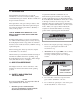
1.1 INTRODUCTION A replacement manual is available from your authorized Scag Service Dealer or by contacting: Scag Power Equipment, Service Department at P.O. Box 152, Mayville, WI 53050. You may also contact us through our website at www.scag.com. The manual for this grass catcher can be downloaded by using the model and serial number or use the contact form to make your request. Please indicate the complete model and serial number of your Scag product when requesting replacement manuals.
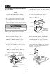
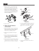
3.1 ASSEMBLY INSTRUCTIONS FOR 61" CUTTER DECK 4. Install the grass catcher pulley onto the spindle assembly. Apply loctite to both pulley setscrews and tighten. See Figure 3-1. -NOTEUse the illustrated parts list as a part number reference when following the assembly instructions. 5. Remove the "Custom-Cut" and "Turbo" baffles from the cutter deck. Using the original hardware, install the new "Front" and "Turbo" baffles. See Figure 3-2. 1. Remove all packaging materials.
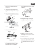
7. Install the blower assembly to the mounting bracket and secure with the mounting pin. See Figure 3-4. 12. Install the hopper mounting brackets to the outside of the frame on the rear of the machine. See Figure 3-6. 8. Align the blower assembly with the discharge opening of the cutter deck. Tighten the hardware for the mounting bracket. See Figure 3-4. Hopper Mounting Brackets Rear Frame 9. Install the quick pin through the rear hole in the discharge chute mounting bracket. See Figure 34.
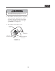
17. Install one 7/16-14 x 1-3/4" hex head bolt into each of the four mounting holes in the weight support bar, and through the matching holes in the caster support weldment. Secure this assembly to the front of the machine using the 7/16 - 1/2" x 1-1/4" x .083" flatwashers, and the 7/16-14 elastic stop nuts. Torque hardware to 59 ft. lbs. See Figure 3-8.
WARNING DO NOT OPERATE WITHOUT DISCHARGE CHUTE, MULCHING KIT, OR ENTIRE GRASS CATCHER INSTALLED 7. Re-install the side discharge chute to the opening on the cutter deck. Replace the two outside mounting bolts on the discharge chute with the clevis pins (p/n 04064-15) and rue cotter pins (p/n 04069-03). See Figure 4-3. 8. Re-install the cutter deck belt cover.
MAINTENANCE 5.
NOTES 7
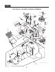
GC-STWC-61V BLOWER HOUSING ASSEMBLY 9 10 8 4 12 45 1 2 11 48 14 3 13 11 9 11 7 10 47 10 44 14 27 14 12 11 15 43 16 42 26 41 39 18 W FO E B R E E IN V HL O C UA C M A AN M LT 'S E GR B TINATO R LL RAOPE TA E D S PREA IN O 40 14 17 R A N 34 IN G 15 17 R 19 E 14 25 35 28 20 41 21 38 22 17 35 27 23 5 24 46 14 R D N A R E W O L B BEFORE ENGINE CHUTE ENTERING CAN E G S E D A L B BLOWER ROTATING BLADES STOP 24 N A D G IN T A T O R Stop en gine DISC UN
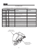
GC-STWC-61V BLOWER HOUSING ASSEMBLY Ref. No. Part Number Description 1 2 3 4 5 6 7 8 9 10 11 12 13 14 15 16 17 18 19 20 21 22 23 24 25 26 04067-10 481547 04066-04 04001-21 481377 482080 481428 483223 04024-02 04021-05 04041-07 43277 483209 04021-09 04030-04 424361 04003-05 04001-46 04001-81 04001-21 461928 483182 483189 04043-04 43575 482871 Pin, Ring 2-1/4" Long Lanyard, Deck Height Pin Quick Pin, 5/16" Dia.
GC-STWC-61V" BLOWER MOUNTING COMPONENTS UNDER SIDE OF VELOCITY-PLUS CUTTER DECK SHOWN 16 16 10 10 11 5 2 26 25 4 6 23 27 23 28 7 1 24 8 3 25 26 25 6 12 13 24 9 21 14 22 20 15 15 16 18 17 19 RIGHT SIDE OF CUTTER DECK SHOWN 2006 GC-STC-V BMC 10
GC-STWC-61V" BLOWER MOUNTING COMPONENTS Ref. No.
GC-STWC-61V BUCKET SUPPORT COMPONENTS (UPPER) 3 36 37 35 1 6 4 2 5 3 9 11 8 33 4 33 5 23 23 32 21 22 16 5 31 9 13 18 19 9 5 16 21 13 16 18 20 16 24 11 14 16 5 4 5 38 9 35 16 25 17 31 9 34 15 30 27 32 29 26 28 12 40 7 12 10 39
GC-STWC-61V BUCKET SUPPORT COMPONENTS (UPPER) Ref. No.
GC-STWC-61V BUCKET SUPPORT COMPONENTS (LOWER) 1 2 24 22 23 21 18 20 19 "A" 3 4 5 17 16 15 6 11 7 TO "A" 13 4 4 4 5 8 6 14 7 12 3 4 8 6 FRAME 9 6 5 4 9 14 10 10A STC 2002 BSC
GC-STWC-61 BUCKET SUPPORT COMPONENTS (LOWER) Ref. No. 1 2 3 4 5 6 7 8 9 10 10A 11 12 13 14 15 16 17 18 19 20 21 22 23 24 Part Number 04090-02 482321 423262 04041-07 04021-09 04020-04 04021-05 04067-07 04001-19 451726 451725 04021-02 04001-46 04001-31 482569 423312 451674 04003-02 04001-08 423198 04003-12 423197 04019-03 04040-15 04021-10 Description Pop Rivet, 3/16 x .652 Seal, Hood Tube, Upright Flatwasher, 3/8-.391 x .938 x .
GC-STC DECALS 482871 482871 482275 MANUFACTURED UNDER ONE OR MORE OF THE FOLLOWING PATENTS: 4,487,006 4,991,382 5,133,176 6,192,666 4,885,903 4,998,948 5,826,416 6,766,633 4,920,733 5,042,239 5,832,708 6,892,519 4,967,543 5,118,617 5,865,018 PATENTS PENDING 483044 481327 481377 483037 482080 482080 16
LIMITED WARRANTY- COMMERCIAL ACCESSORY Any part of the Scag commercial accessory manufactured by Scag and found, in the reasonable judgment of Scag, to be defective in material or workmanship, will be repaired or replaced by an Authorized Scag Service Dealer without charge for parts and labor. The Scag accessory, including any defective part, must be returned to an Authorized Scag Service Dealer within the warranty period.
© 2005 SCAG POWER EQUIPMENT DIVISION OF METALCRAFT OF MAYVILLE, INC. WWW.SCAG.COM PART NO.