THIS MANUAL CONTAINS THE OPERATING INSTRUCTIONS AND SAFETY INFORMATION FOR YOUR SCAG ACCESSORY. READING THIS MANUAL WILL PROVIDE YOU WITH MAINTENANCE AND ADJUSTMENT PROCEDURES TO KEEP YOUR ACCESSORY PERFORMING TO MAXIMUM EFFICIENCY. THE SPECIFIC MODELS THAT THIS BOOK COVERS ARE CONTAINED ON THE INSIDE COVER. BEFORE OPERATING YOUR MACHINE, PLEASE READ ALL THE INFORMATION ENCLOSED.
WARNING FAILURE TO FOLLOW SAFE OPERATING PRACTICES MAY RESULT IN SERIOUS INJURY. * Keep all safety shields in place. * Before performing any maintenance or service, stop the machine and remove the spark plug wire. * If a mechanism becomes clogged, stop the engine and wait for all moving parts to come to a complete halt before cleaning. * Keep hands, feet and clothing away from power-driven parts. * Read this manual completely as well as the Operator's Manual that came with your mower.
1.1 INTRODUCTION A replacement manual is available from your authorized Scag Service Dealer or by contacting: Scag Power Equipment, Service Department at P.O. Box 152, Mayville, WI 53050. You may also contact us through our website at www.scag.com The manual for this grass catcher can be downloaded by using the model and serial number or use the contact form to make your request. Please indicate the complete model and serial number of your Scag product when requesting replacement manuals.
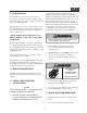
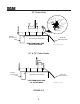
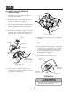
5. To clean the hopper debris screen; 3. When dumping the hopper into a disposal area: WARNING A. Disengage the deck drive and allow all moving parts to come to a complete stop. B. Apply parking brake and shut off the engine. C. Stand on the left side of the hopper assembly. D. Unhook the debris screen latches and remove the debris screen from the hopper. See Figure 2-3. DO NOT DUMP CLIPPINGS IN A DISPOSAL AREA THAT IS BURNING A. B.
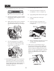
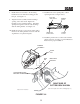
3.1 ASSEMBLY INSTRUCTIONS 3. Remove the right side belt cover to gain access to the spindle assembly. Remove the u-nuts from the cutter deck bracket. See Figure 3-1. -NOTEUse the illustrated parts list as a part number reference when following the assembly instructions. 4. Install the grass catcher pulley onto the spindle assembly. Apply loctite to both pulley setscrews and tighten. See Figure 3-1. 1. Remove all packaging materials.
52" Cutter Deck LIFT LINK BELL CRANK NUT SPACER BOLT, 3/8-16 x 1-1/4" BOLT, 3/8-16 x 1-1/2" WASHER SPACER NUT CUTTER DECK REAR OF CUTTER DECK DISCHARGE CHUTE OPENING VIEW FROM RIGHT SIDE OF CUTTER DECK FRONT OF CUTTER DECK Figure 2-52"GC-STT install art 61" & 72" Cutter Decks REAR OF CUTTER DECK P R O P E R Y L S E C R E V I E N G E I W T H I OL I A N D DISCHARGE F CHUTE OPENING U EL.
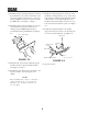
11. Install the belt to the spindle pulley. When replacing the belt, see figure below. 8. Install the blower assembly to the mounting bracket and secure with the mounting pin and hair pin. See Figure 3-4. BACK SIDE IDLER PULLEY 9. Align the blower assembly with the discharge opening of the cutter deck. Tighten the hardware for the mounting bracket. Install the quick pin through the rear hole in the discharge chute mounting bracket. See Figure 3-4. 10.
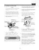
13. Install the hopper mounting brackets (p/n 451512 17. Install the weight support bar to the front of the & p/n 451595) to the outside of the frame on the machine by resting it directly on top of the caster rear of the machine using 3/8-16 x 1" hex head support arms and sliding it tight against the frame bolts (p/n 04001-19) and 3/8-16 elastic stop nuts of the machine. Secure the weight bar to the (p/n 04021-09). See Figure 3-7, Page 7.
Item # 1 2 3 4 5 Part # 04001-19 04021-09 04066-03 423670 451512 451595 Description Bolt, Hex Head 3/8-16 x 1" Nut, Elastic Stop 3/8-16 Quick Pin Spacer, Hitch Hitch Bracket Weldment Hitch Bracket Weldment, Floating Hopper Assembly 5 1 2 3 Liquid Cooled Only 2 1 4 1 Note: Illustration is for reference only. Some parts have been removed for visual purposes and may vary depending on model.
6.1 GRASS CATCHER REMOVAL INSTRUCTIONS 1. Prepare the work area making sure that it is a clean, safe environment. REMOVE 2. Remove the rubber strap holding the adapter to the blower assembly. See Figure 5-1. 3. Remove the belt from the spindle pulley and the quick pin securing the blower to the discharge mounting bracket. OD UT HO Y O LL MBL U P SE AS REMOVE 4. Remove the pin and hair pin securing the blower assembly to the mounting bracket on the cutter deck and remove the blower assembly.
MAINTENANCE 5.
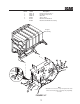
GC-STT-V BLOWER HOUSING ASSEMBLY 9 10 8 4 12 48 1 2 11 49 14 50 13 11 9 11 7 10 47 10 44 14 27 14 12 11 15 43 16 42 41 39 18 W FO E B R E E IN V HL O C UA C M A AN M LT 'S E GR B TINATO R LL RAOPE TA E D S PREA IN O 40 14 17 26 R A N 34 IN G 15 17 R 19 E 3 25 28 20 41 21 38 22 17 35 27 23 5 24 46 14 D N A R E W O L B BEFORE ENGINE CHUTE ENTERING CAN R BLOWER ROTATING BLADES STOP E G S E D A L B en gine DISC UN DO NO be LE HA SS T OP fore cl RG G
GC-STT-V BLOWER HOUSING ASSEMBLY Ref. No. Part Number Description 1 2 3 4 5 6 7 8 9 10 11 12 13 04067-07 481547 04019-02 04001-59 481377 482080 481428 483223 04024-02 04021-05 04041-07 43277 483173 483209 04021-09 04030-04 424361 04003-05 04001-54 04001-81 04001-21 461xxx 461928 483182 483189 04043-04 43504 43575 482871 481039 Pin, Ring 2-1/4" Long Lanyard, Deck Height Pin Nut, Serr.
GC-STT-V BLOWER MOUNTING COMPONENTS UNDER SIDE OF VELOCITY-PLUS CUTTER DECK SHOWN 16 16 10 10 11 5 2 26 25 4 6 23 27 23 28 7 1 24 8 3 25 26 25 6 12 13 24 9 21 14 22 20 15 15 16 18 17 19 RIGHT SIDE OF CUTTER DECK SHOWN 2006 GC-STC-V BMC 12
GC-STT-V BLOWER MOUNTING COMPONENTS Ref. No.
GC-STT-CSV HOPPER COMPONENTS 16 14 49 50 45 45 5 4 3 41 15 31 43 11 51 17 56 55 40 58 59 8 12 9 6 50 B 55 34 42 24 27 43 49 53 18 38 49 34 61 48 38 53 49 50 52 41 54 12 18 53 49 58 59 28 34 49 69 38 49 45 49 49 38 21 33 53 19 64 53 57 35 13 46 37 C 23 26 44 B 49 46 A 46 49 58 59 57 65 71 38 22 49 63 61 29 35 37 68 30 32 67 49 21 32 49 49 20 59 33 66 49 25 36 58 7 1 49 40 49 53 38 33 19 C A 62 10 36 20 60 61 37 60 72 7
GC-STT-CSV HOPPER COMPONENTS Ref. No.
GC-STT-CSV DECALS 481039 482275 483044 481327 481377 483037 482080 16
LIMITED WARRANTY- COMMERCIAL ACCESSORY Any part of the Scag commercial accessory manufactured by Scag and found, in the reasonable judgment of Scag, to be defective in material or workmanship, will be repaired or replaced by an Authorized Scag Service Dealer without charge for parts and labor. The Scag accessory, including any defective part, must be returned to an Authorized Scag Service Dealer within the warranty period.
© 2005 SCAG POWER EQUIPMENT DIVISION OF METALCRAFT OF MAYVILLE, INC www.scag.com PART NO.