
Specifications


HW400p/M Technical Reference - 1.0, March 6, 2002 CPLD Registers 45
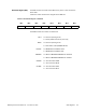
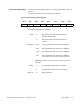
Board Status Register (BSR) The BSR controls two board status LEDs on the panel. It also controls the
Power LED.
Table 5-11 shows the functions assigned to the BSR bits.
The BSR functions and states are defined as:
Table 5-11 Board Status Register – FFE20005
Bit 7Bit 6Bit 5Bit 4Bit 3Bit 2Bit 1Bit 0
Reserved FACT Reserved DARK PRTYPE EEPWEN STLEDB STLEDA
FACT 0 = Normal operating mode
1 = Factory Mode (For Factory Use Only)
DARK 0 = Normal operating mode
1 = Dark Office mode (POWER LED off)
PRTYPE 0 = MPC8245 boot PROM is flash
1 = MPC8245 boot PROM is OTP
EEPWEN 0 = Writes to MPC8245 EEPROM are disabled
1 = Writes to MPC8245 EEPROM are enabled
STLEDB 0 = Turn off Status LED B
1 = Turn on Status LED B
STLEDA 0 = Turn off Status LED A
1 = Turn on Status LED A