
Specifications


44 Programming Information HW400p/M Technical Reference - 1.0, March 6, 2002
Interrupt Enable Register A (IERA) The Interrupt Enable Register A (IERA) contains an interrupt enable mask. The
device interrupt status appears in the interrupt source registers. Setting a “1”
to any of the bits enables the corresponding interrupt
Table 5-9 shows the interrupts assigned to the IERA.
The IER interrupts are defined as:
Note:
For all: 1= Enabled, and 0 = Disabled.
Interrupt Enable Register B (IERB) The Interrupt Enable Register B (IERB) is a read/write register. This register
allows the MPC8245 to mask or unmask interrupts. Setting a “1” to any of the
bits enables the corresponding interrupt.
Table 5-10 shows the interrupts assigned to IERB.
The IERB interrupts are defined as:
Note: For all: 1= Enabled, and 0 = Disabled
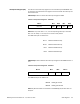
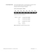
Table 5-9 Interrupt Enable Register A – FFE20003
Bit 7–4 Bit 3Bit 2Bit 1Bit 0
Reserved IE11 IE10 IE9 IE8
IE11 PMC Site INTD Interrupt
IE10 PMC Site INTC Interrupt
IE9 PMC Site INTB Interrupt
IE8 PMC Site INTA Interrupt
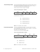
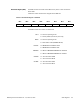
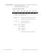
Table 5-10 Interrupt Enable Register B – FFE20004
Bit 7–4 Bit 3 Bit 2 Bit 1–0
Reserved IE3 IE2 Reserved
IE3 DUART B Interrupt
IE2 DUART A Interrupt