
Specifications


HW400p/M Technical Reference - 1.0, March 6, 2002 AMD Ethernet Controller Register Map 41
5-4. AMD Ethernet Controller Register Map
For the Am79C973 register map and further information, see the
AMD
Am79C973/Am79C975 PCnet-Fast III Single-Chip 10/100 Mbps PCI Ethernet
Controller with Integrated PHY product manual. The URL for the AMD website
is http://www.amd.com.
5-5. Intel 21554 Register Map
For more information, see the Intel
21554 PCI-to-PCI Bridge for Embedded
Applications Hardware Reference Manual. The URL for Intel’s website is
http://www.intel.com.
5-6. MPC8245 Interrupt Assignments
All interrupts are latched into an interrupt register resident in the CPLD. The
CPLD generates INT0–INT4, which are read by the MPC8245 via the Epic
Interrupt interface. See MPC8245 interrupt routing in Section 5-7, and the
Motorola MPC8245 Integrated Processor User’s Manual Rev 1.0.
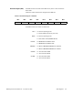
MPC8245 interrupt routing
The Embedded Programmable Interrupt Controller (EPIC) within the MPC8245
must be programmed to accept interrupts in discrete IRQ mode. See
Table 5-5.
Note: The “Active Level” column indicates the high or low active state of the
interrupt as generated by the device.
Table 5-5 Interrupt pin functions
Pin Description Active Level
INT 0 MPC8245 Pushbutton Interrupt Low to High Edge
INT 1 Combined Interrupts (see Interrupt Source
Register (ISR)
in Section 5-7)
High Active
INT 2 PMC Site INTA Interrupt Low Active
INT 3 Ethernet Interface Low Active
INT 4 PCI bridge 21554 Low Active