
Specifications


HW400p/M Technical Reference - 1.0, March 6, 2002 Connectors 29
Power up and reset A microprocessor supervisory manager provides the power up reset. The
device monitors both 3.3V and 2.0V levels and issues a reset if either voltage
falls below its specification.
The reset is active for 100ms. The reset generates other logical resets. This
reset logic resides in the CPLD to provide system reset as the result of power
up reset and pushbutton reset.
The CPLD reset manages the various reset signals to all devices. After power
up, all devices are held in a reset state for 100ms (minimum). Beyond the
power up reset, all devices can be reset by the host via the PCI bus or by a
pushbutton switch.
Table 4-5 shows all reset types and which devices are affected.
4-8. Connectors
Ethernet connector The ethernet connector is a standard RJ45 connector. It is not front panel
accessible.
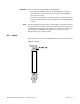
PCI connectors
PCI connector P1 pin assignments.
Table 4-6 shows the standard PCI bus
connector pin assignments for a 64-bit PCI card where the direction is with
respect to the PCB.
Note: The # symbol indicates an active LOW signal.
Table 4-5 Devices affected by power up and reset types
Reset MPC8245 CPLD Ethernet DUART 21554
MPC8245
Pushbutton*
XXXX
Host PCI X X X X X
Power Up X X X X X
* Pushbutton reset requires the console accessory kit