
Specifications


24 Functional Information HW400p/M Technical Reference - 1.0, March 6, 2002
4-4. LEDs
A dual-color board-status LED visible from the front panel of the HW400p/M
PCI is controlled by the MPC8245 via the Board Status Register (BSR) in the
CPLD.
See Table 4-2 for a chart of the LED functions and physical descriptions.
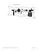
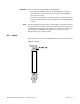
Figure 4-3 shows the board LEDs.
Table 4-2 LEDs
LED Function Qty Color Description
Ethernet
EthernetEthernet
Ethernet
Ethernet Link Pass LED
(LAN)
1 Green Controlled by the Am79C973 Ethernet
controller; indicates an active link.
Ethernet Collision LED
(LAN)
1 Green Controlled by the Am79C973;
indicates a collision.
Ethernet Active LED 1 Green Controlled by the Am79C973;
indicates Ethernet activity.
Ethernet 100BaseT Mode
LED
2 Green Controlled by the Am79C973;
indicates 100 Base-T.
General Board Status
General Board StatusGeneral Board Status
General Board Status
Power Good LED (PWR) 1 Green Indicates good power (above the
minimum voltage tolerance). Can be
turned off by Dark Office if desired.
STATUS LED 1 Green/
Yellow
(dual color)
Controlled by MPC8245; visible from
the front panel.
Development
DevelopmentDevelopment
Development
General Purpose LED Array 8 Green Controlled by MPC8245.
Surface-mounted near the top edge of
the board next to the Flash sockets.
See LED Registers (LED) on page 46.