
Specifications


HW400p/M Technical Reference - 1.0, March 6, 2002 MPC8245 21
4. Functional Information
4-1. MPC8245
Development/debug support Development and debug support is provided in the console accessory kit. A
COP header is also provided on board. See Section 4-9.
Reset The following types of reset are available on the MPC8245:
•Power-on reset.
• Host accessible reset, which allows the host on the PCI bus to reset only
the board’s local bus.
• External pushbutton reset via a special SBE reset/interrupt cable on the
console accessory kit.
Download and console ports The console accessory kit connects to a 30-pin EBBI connector located along
the top edge of the HW400p/M. The console accessory kit provides external
pushbutton reset and interrupt along with download and console ports.
Table 4-7 shows the pin assignments for the processor’s debug port
connector.
4-2. PMC Site
Compatible PMC modules The PMC site on the HW400p/M accepts a single wide (149mm x 74mm)
module of either the PMC32 or PMC64 type. PMC64 modules operate in
32-bit mode when fitted to the HW400p/M. Both 3.3V and 5V PCI signaling
modes are supported (see Voltage keying). The HW400p/M supports front
panel I/O access only. Pn3/Jn3 and Pn4/Jn4 user I/O connections are not
supported.
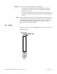
Voltage keying PCI signaling voltage is selected using a voltage key post that mechanically
prevents a signaling voltage mismatch between the module and HW400p/M.
The voltage key is attached to one of two positions using a screw through the
board.