
Specifications

Smart Battery Charger Specification
SBS Implementers Forum -Page 3- Revision 1.1
4. Smart Battery Charging System
A Smart Battery Charging System at a minimum consists of a Smart Battery and Smart Battery Charger
compatible with this specification and those described in the references section.
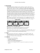
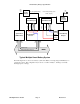
4.1. Smart Battery System Block Diagrams
A system may use one or more Smart Batteries. The block diagram of a Smart Battery Charging System
shown below (notebook computer, video camera, cellular phone, or other portable electronic equipment)
depicts a single battery system. For more details about the system components and interactions, see the
Smart Battery Data Specification (refer to the References section).
System Host
(SMBus Host)
System
Power
Supply
Smart Battery
Charger
Vcc,
+12v,
-12v
Critical Events
Battery Data/Status Requests
SMBus
AC-DC
Converter
DC (Unregulated)/Vbattery
AC
Typical Single Smart Battery System
(Unregulated)
Critical Events
Smart Battery
System Power
Control
DC (Unregulated)
Vbattery
Safety
Signal
Charging Voltage/Current
Requests
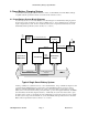
Another possibility is a system that uses two or more Smart Batteries. One possible block diagram of such
a system featuring multiple batteries is shown below. The Smart Battery Selector is used to connect
batteries to either the Smart Battery Charger, the system or disconnect them, as appropriate. For each
battery, three connections must be made, power (the battery’s positive and negative terminals), the SMBus
(Clock and Data) and the Safety Signal (resistance). Additionally, the system host must be able to query
any battery in the system so it can display the state of all batteries present in the system. For more details
about the system components and interactions, see the Smart Battery Data Specification and/or the Smart
Battery Selector Specification (refer to the References section).