
Specifications

Smart Battery Charger Specification
SBS Implementers Forum -Page 19- Revision 1.1
6. Smart Battery Charger Characteristics
Smart Battery Chargers are differentiated by their type (see Smart Battery Charger types in this document).
Each type has certain characteristics and supports certain functions. This section describes the
characteristics and functions all chargers have in common as well as those that are type specific.
6.1. Common Smart Battery Charger Characteristics
All Smart Battery Chargers have the following capabilities, characteristics and options in common.
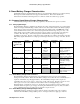
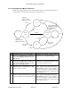
6.1.1. Safety Signal Ranges
The Smart Battery Charger’s capabilities are altered by the value of the Safety Signal. As a required safety
feature, the charger must NOT charge a battery when it senses the resistance between the Safety Signal pin
and ground to be in the range between 575 and 2850 ohms. The Safety Signal of a NiMH battery which
uses a 103AT thermistor as the source of the Safety Signal would enter this range if it got too hot; or the
Safety Signal of a Li-ion battery which uses discrete resistors could be set to this range in an emergency
condition. The valid ranges of the Safety Signal are summarized below along with the charger’s
capabilities for the range. Note the overlap in the ranges, which allow for tolerance in detecting each range.
If the Safety Signal value falls in an overlap region, the charger must detect one range or the other, but not
both.
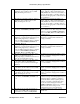
Safety Signal
resistance, Rss
(ΩΩ)
Charger
Status Bits
Description “Wake-up”
charge
“Controlled”
charge
Notes
0 < Rss <575 RES_UR,
RES_HOT
under-range allowed for
initial
time-out
period
allowed Charger can “wake-up”
charge for time-out
period; “controlled”
charge allowed.
425 < Rss < 3150 RES_HOT Hot not allowed not allowed Fail-safe charge
termination -- charger
must not supply current
2850 < Rss < 31.5k (none) Normal range allowed
indefinitely
allowed Charger can “wake-up”
charge indefinitely;
“controlled” charge
allowed.
28.5k < Rss < 105k RES_COLD Cold allowed for
initial time-
out period
allowed Charger can “wake-up”
charge for time-out
period only.
Rss > 95k RES_OR,
RES_COLD
over-range not allowed not allowed Can be used as battery
detect; charger does not
supply current.
6.1.2. Smart Battery Charger Time-out Period
The Smart Battery Charger detects that it has lost communication when it does not receive charging
messages in a timely manner. When the Smart Battery Charger detects that it has lost communications, it is
required to immediately stop charging the battery. The Smart Battery Charger’s time-out period is
nominally 175seconds, ±35 seconds (e.g., in the range of 140 - 210 seconds). The time-out period is reset
when a power-on reset occurs, a battery is inserted and/or when new ChargingVoltage() and
ChargingCurrent() commands are received. A shorter time-out period is allowed, however, battery pack
electronics that are designed to get enough power during the minimum timeout period (140s) to be able to
restore communications may not wake-up if a shorter time-out period is used.
6.1.3. Smart Battery Charger Wakeup Charge Current
Smart Battery Chargers are allowed to apply a wake-up current to the battery under some conditions
defined in the Smart Battery Charger Start-up section. A charger is allowed to supply up to 100 mA.