
Operating Guide

2 | P a g e
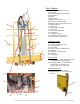
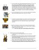
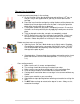
UParts Diagram
1. Retraction Mechanism with spool
2. Cord Holder
3. Guide tube bracket (top & bottom)
4. Guide tubes -2
5. Dust pan
6. Folding Stand
7. Hinge for folding stand – 2
8. Cross brace for folding stand
9. Measuring tapes on measuring track– 2
10. Material Fence-2
11. Fence lip-2
12. Material rollers (10-18)
13. Center step
14. Accu-Square alignment
15. Frame Vent
16. Transport wheels – 2
17. Horizonal bars of Frame (3-4)
18. Vertical bars of Frame (4-6)
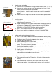
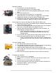
UCARRIAGE & INSERT
19. carriage locks (2)
20. Sealed roller bearings (4)
21. Carriage Frame
22. Insert Plate
23. Trigger lock (not on 2000 series)
24. Saw Motor
25. Dust hood / with dust port
26. Dust hose
27. Carriage pins
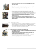
UNOT PICTURED
28. Dual rip gauge – Black banding that runs
along the side of the guide tubes.
29. Rip gauge pointers –2 Bronze metal
pointers that are located on the
carriage near the carriage locks.
UFULLSIZE UNITS ONLY
30. Accu-Fence alignment system
31. Side stand legs – one on each side of
the unit.
1
.
2
.
.
3
.
4
.
6
.
5
.
7
8
9
10
11
12
13
14
15
16
17
18
27
19
20
21
22
23
24
25
26
31
30